Sensor Assembly with Quality Assurance Procedure (QAP)
This document details the Quality Assurance Procedure (QAP) at FloodNet. This document details every stage of the build/assembly procedure to ensure a good sensor build quality.
Table of contents:
- General
- Quality Assurance Procedure
- Stage 1 - PCB Assembly
- Stage 2 - MCU Assembly
- Stage 3 - Battery Assembly
- Evaluation 1 - Main voltage check
- Stage 4 - Housing Preperation
- Stage 5 - Ultrasonic Sensor Assembly
- Stage 6 - PCB Mounting
- Stage 7 - Solar Panel Assembly
- Evaluation 2 - Solar Panel Operation
- Stage 8 - Antenna Assembly
- Evaluation 3 - Sensor Operation
- Final steps
- References
General
Purpose
The main objective of this document is to establish and execute Quality Assurance Procedure (QAP) to produce high quality sensor builds with consistency.
Quality Assurance Procedure
The QAP shall be followed by all the personnel responsible for performing and verifying work affecting sensor quality.
Stage 1 - Housing Preparation
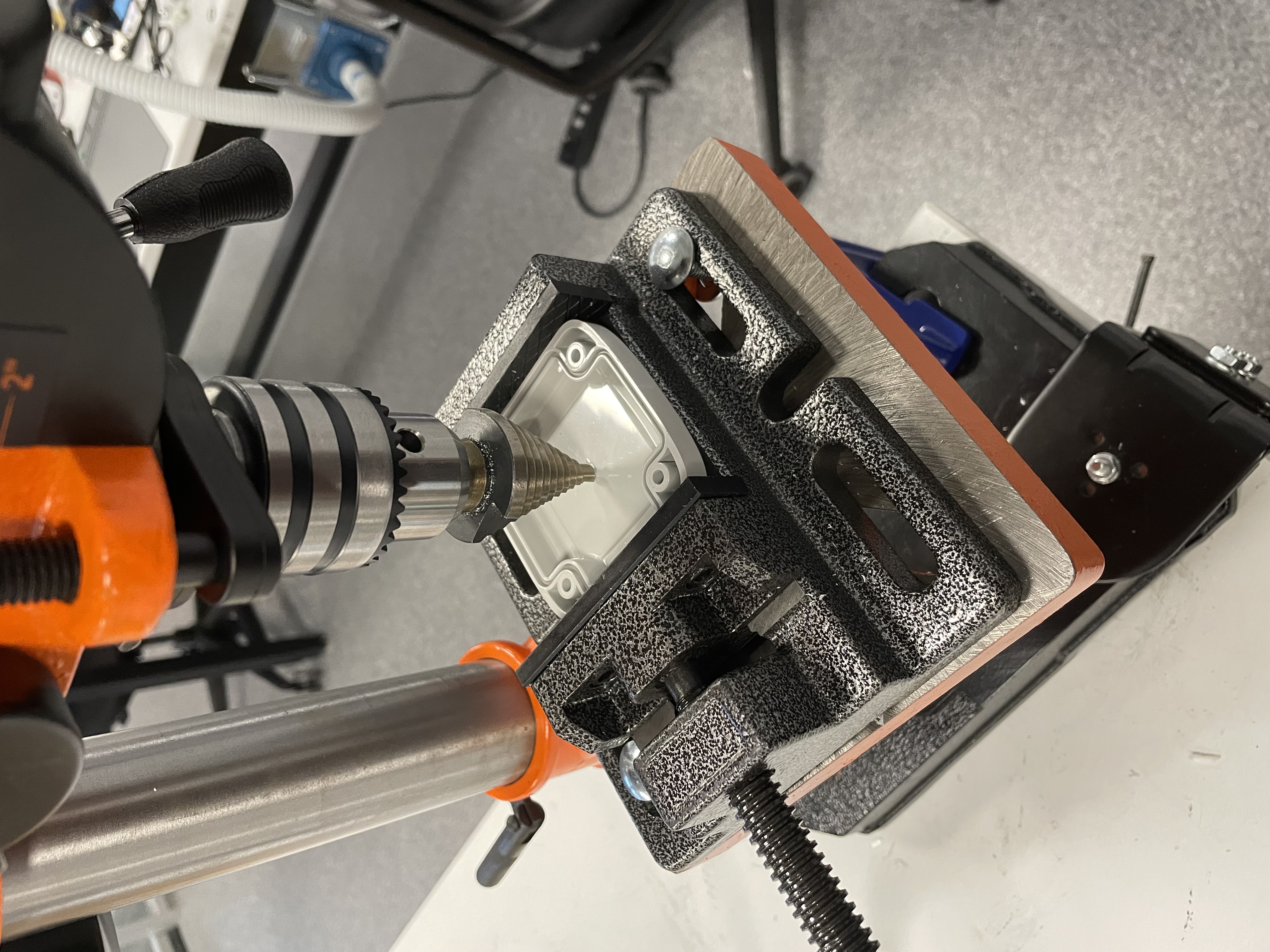
Instructions on using the step drill are here
-
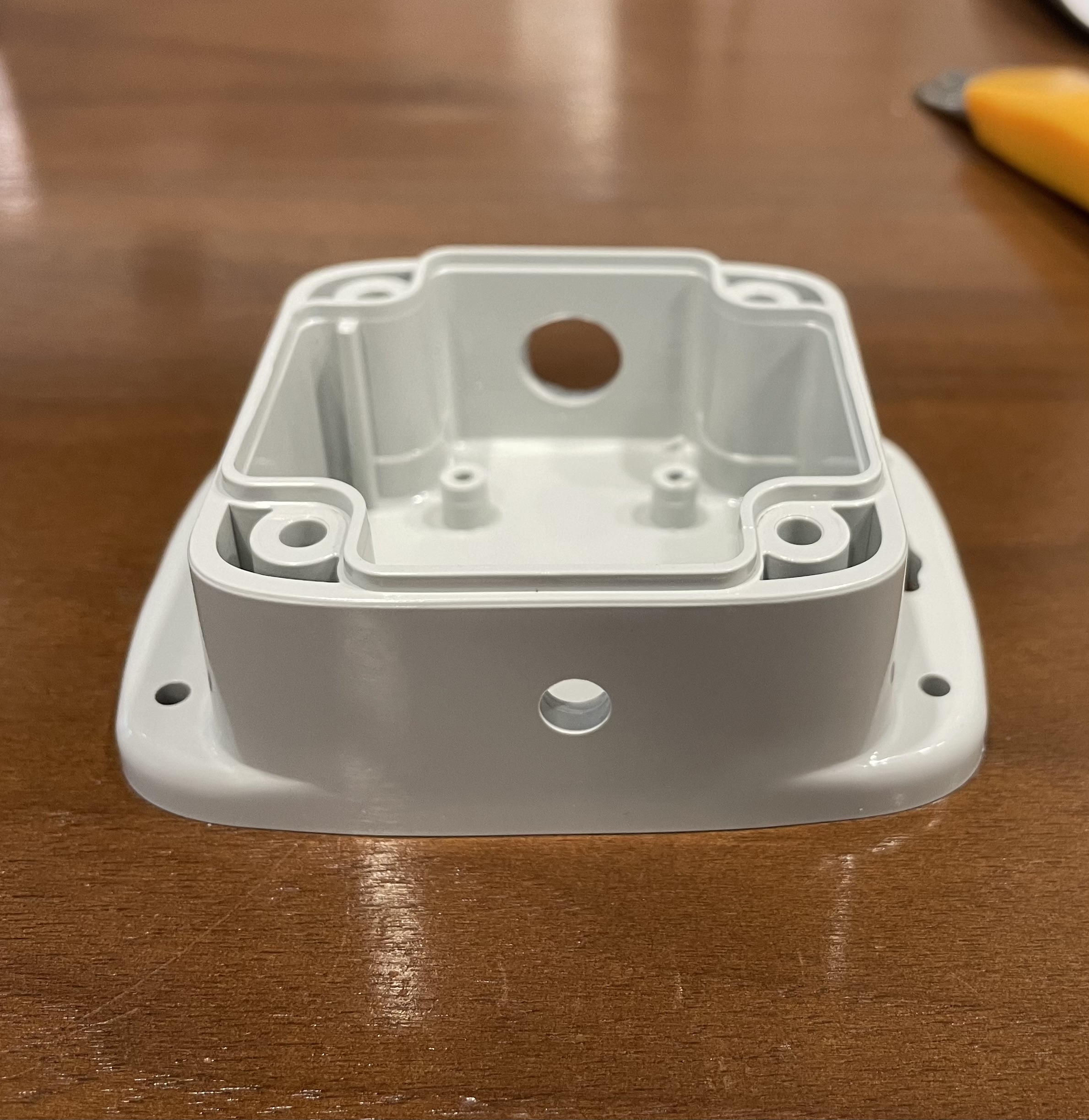
Secure the housing lid using a vice and drill a hole of diameter 1 1/4”.
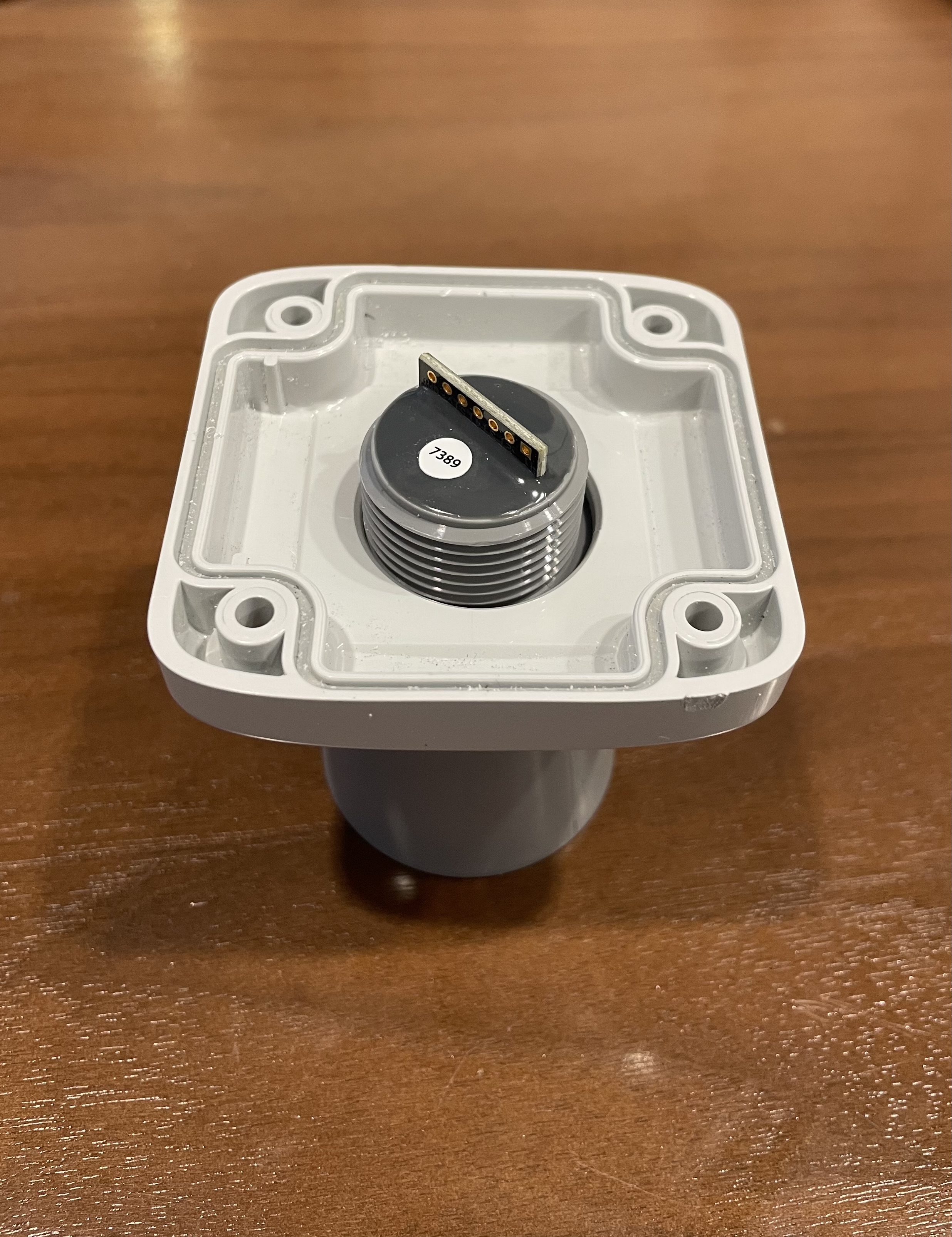
The hole in the lid shall be able accommodate the Ultrasonic sensor.
-
Similarly using a step drill and a vice, on the sides with no mounting support, drill a hole of diameter 1/2” on one side and 1/4” on the other side.
Stage 2 - PCB Assembly
-
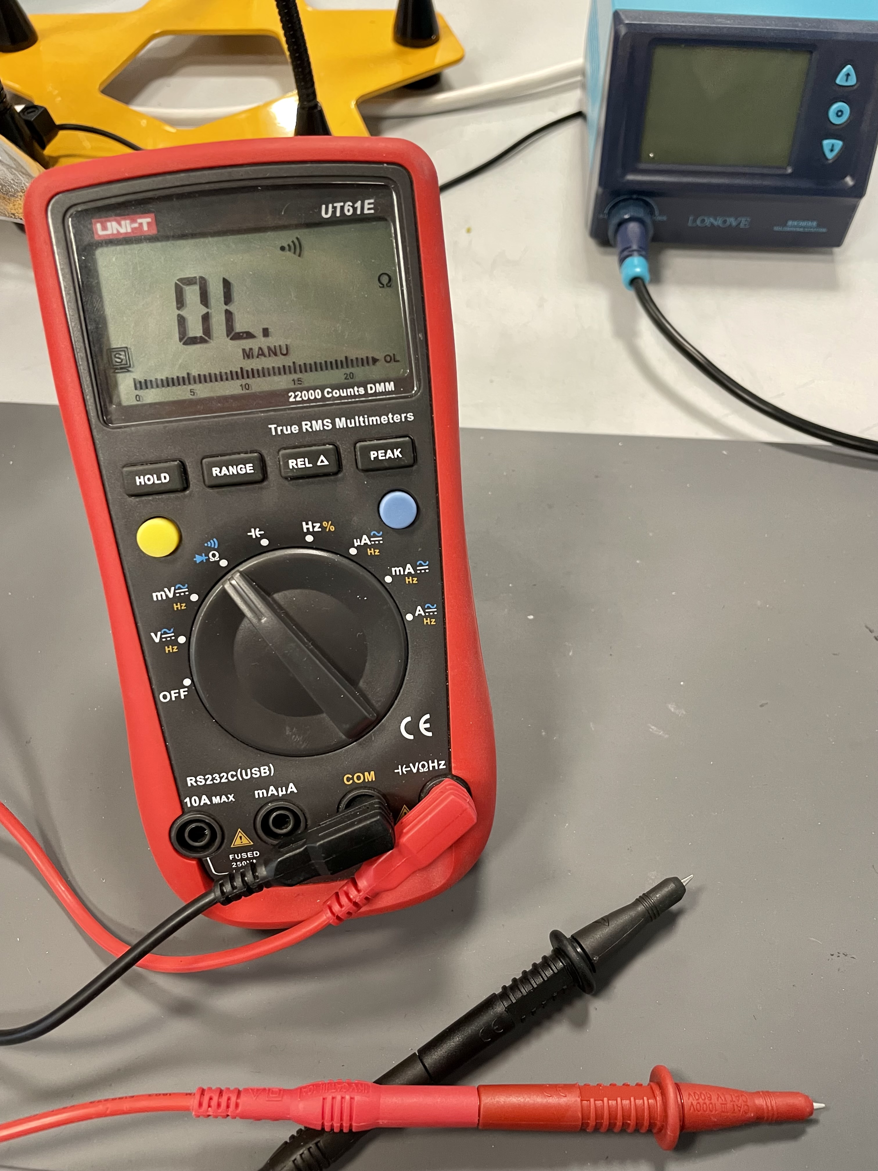
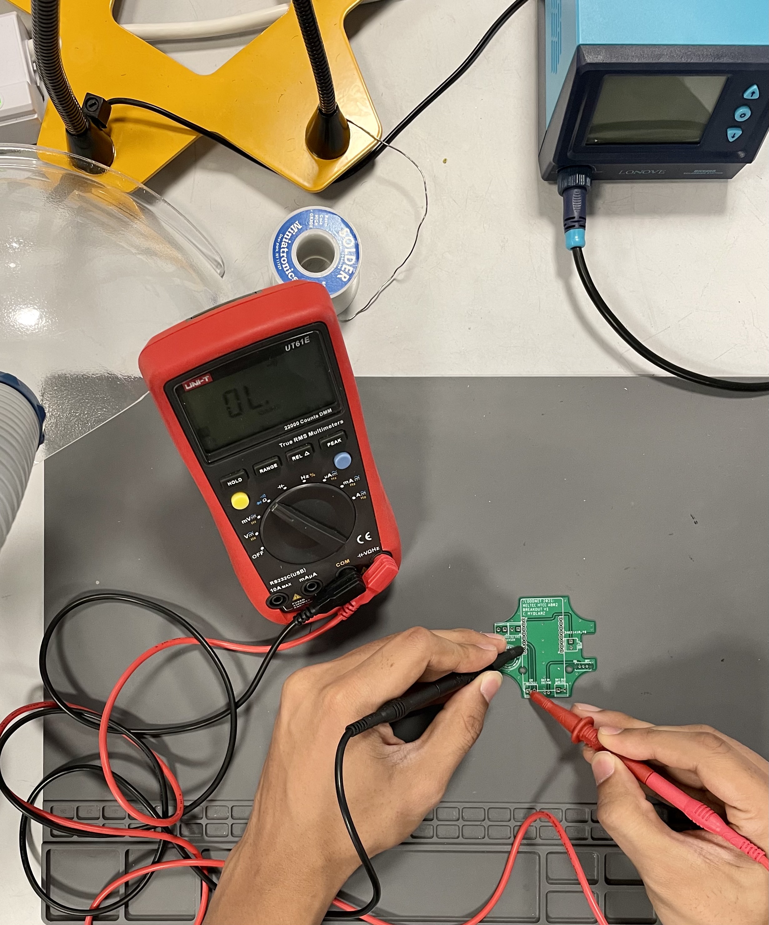
Gather a multimeter and check the PCB for any manufacturing defects. Choose the continuity setting on the multimeter indicated by a small microphone symbol.
To perform the PCB fault check, place one probe on the beginning of the trace and the other on the ending and check for connectivity as shown in the figure below. Repeat this process for every trace.
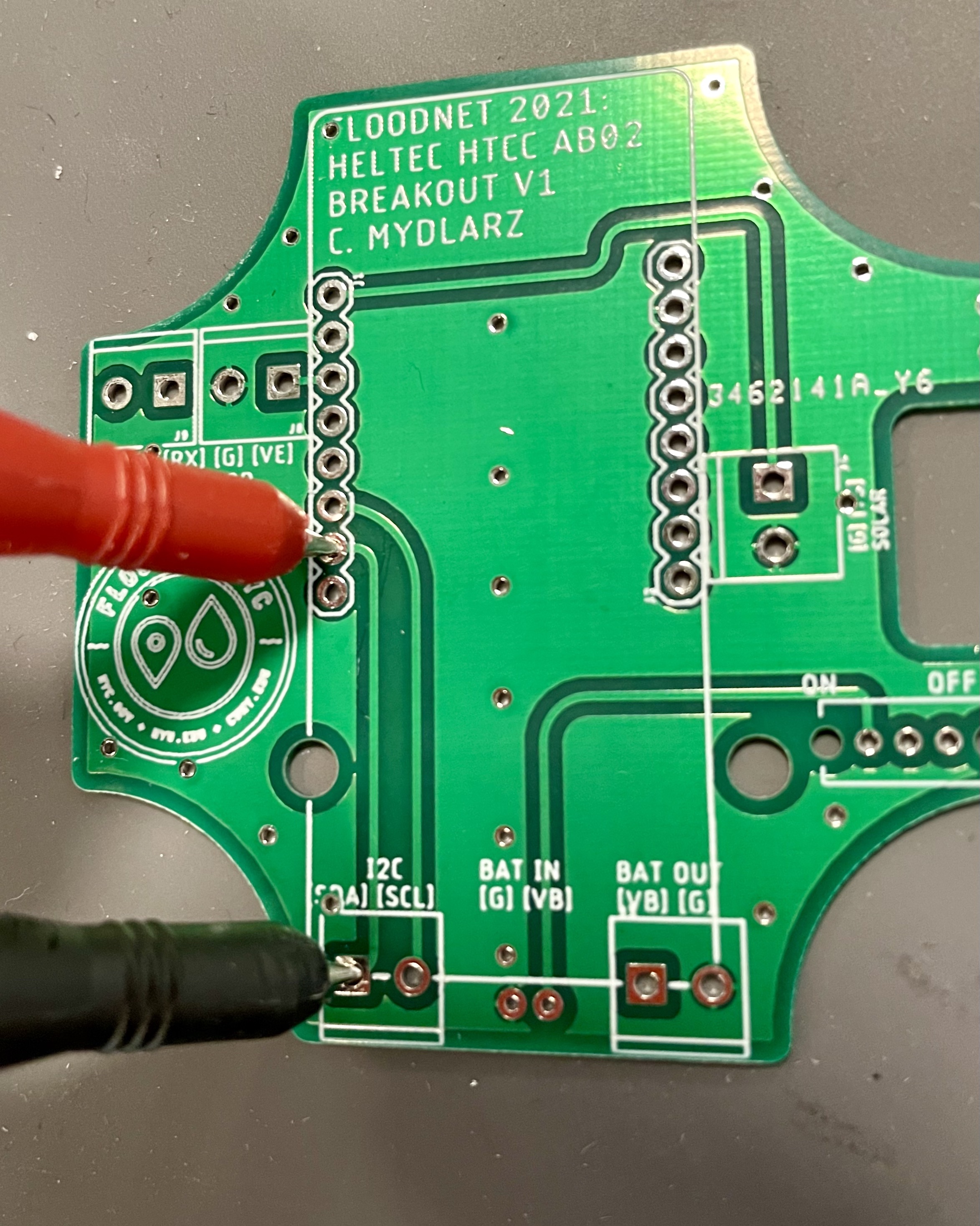
The both ends of a trace shall have connectivity. Across different traces, continuity shall not be observed unless they share the common pin like GND or V+.
-
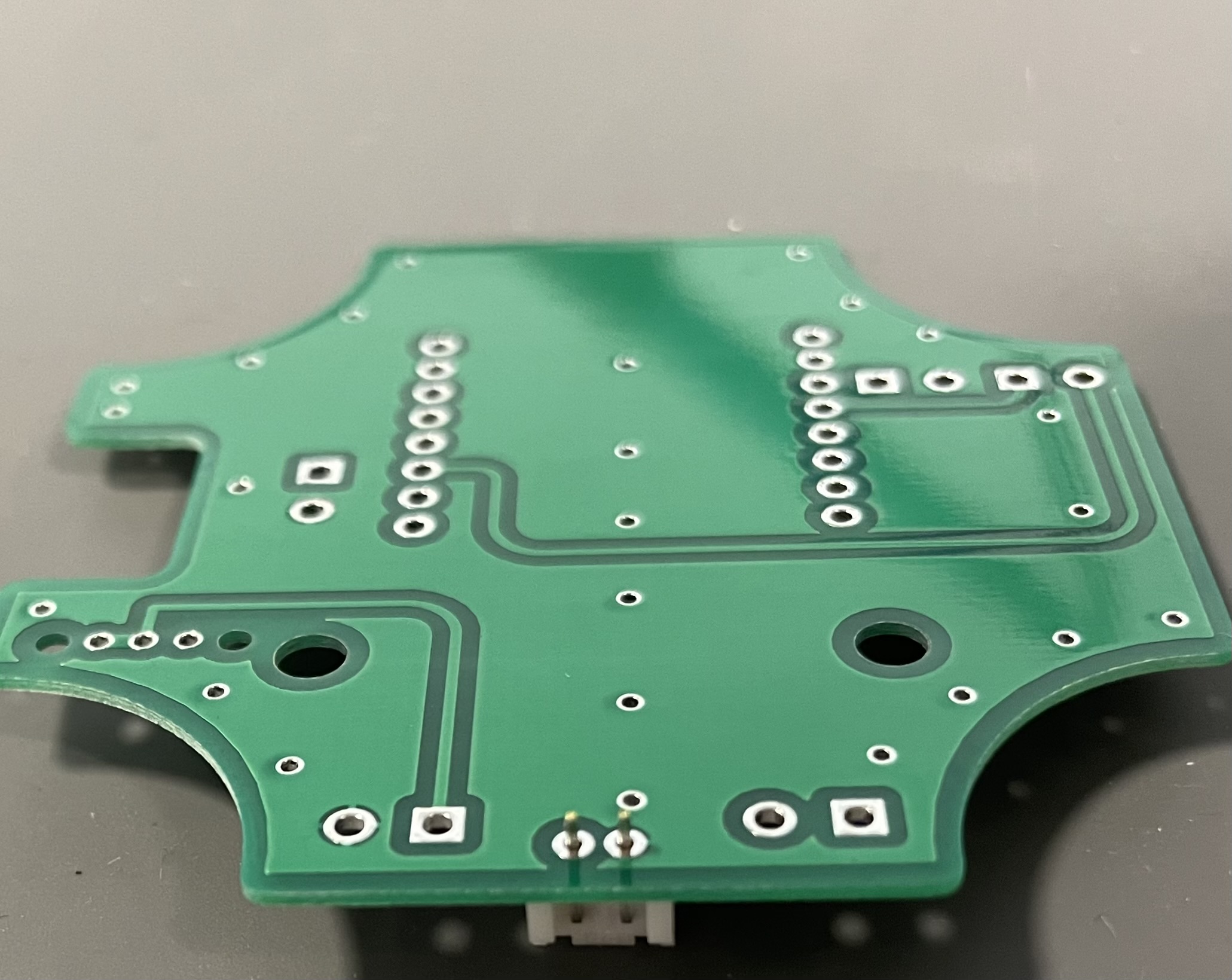
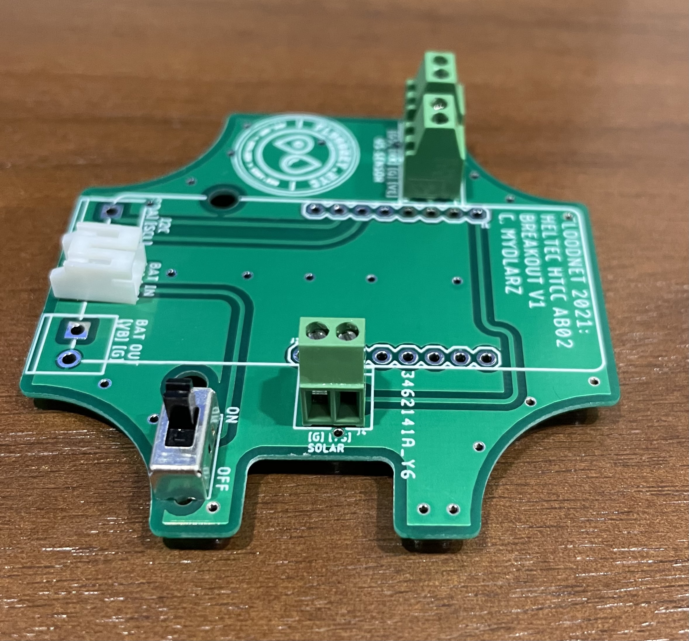
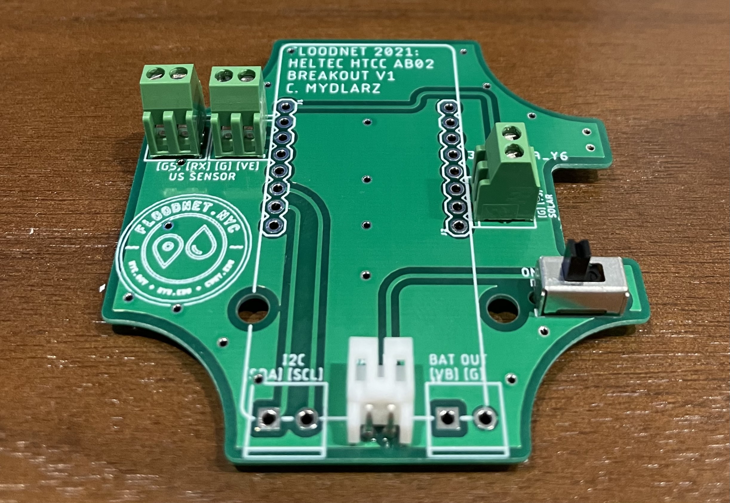
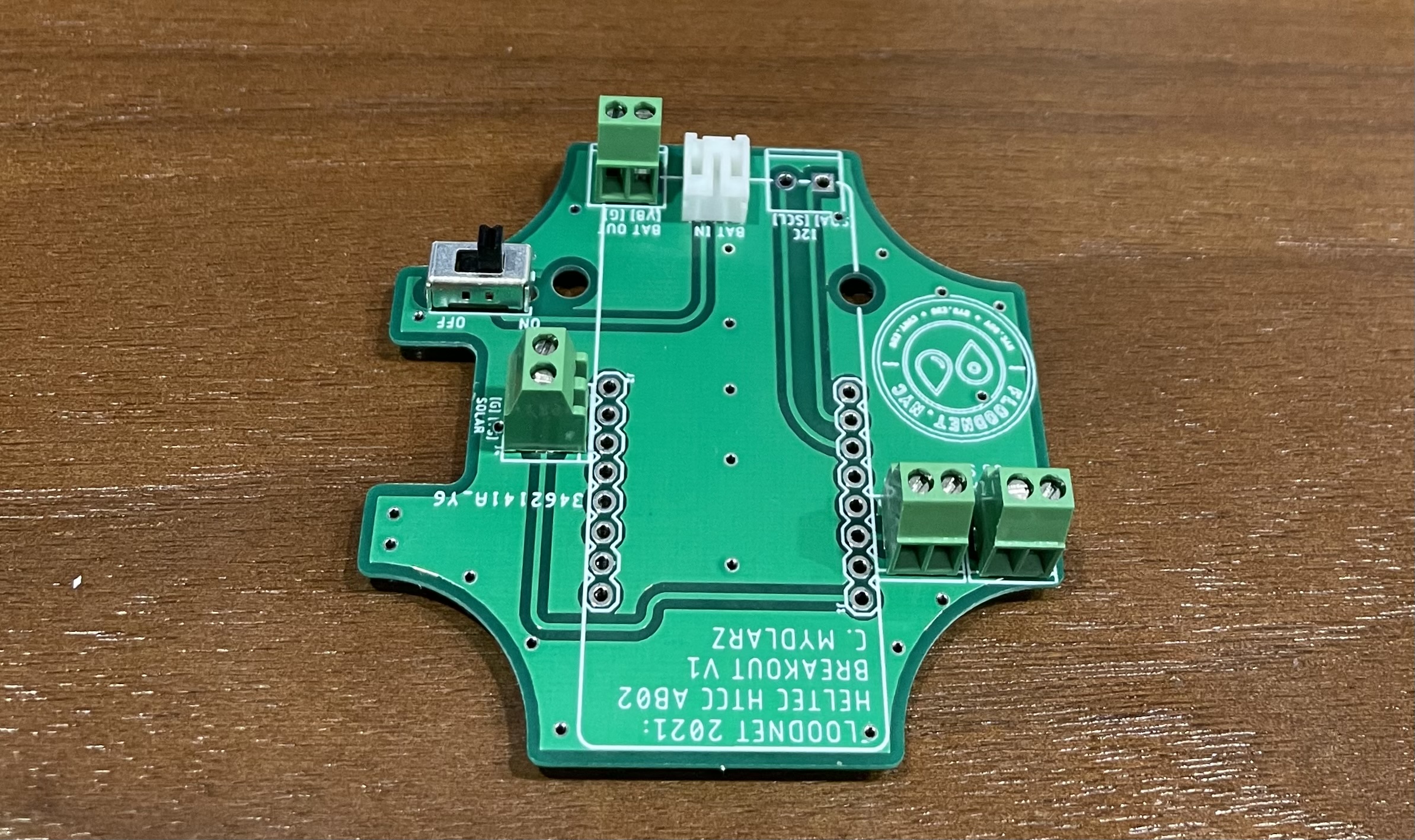
While placing the PCB upside down, Solder a 2-pin JST connector into the Battery IN facing towards the center of the board.
-
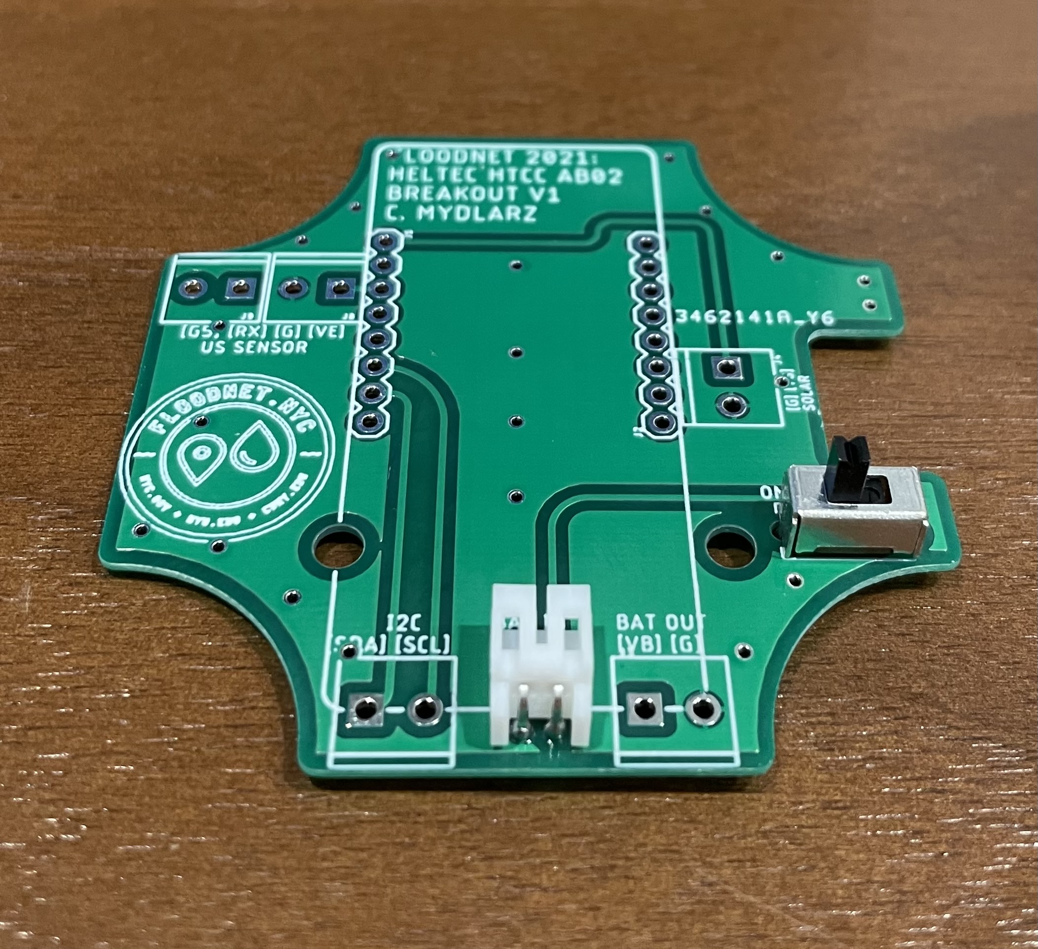
Now with PCB in the same position, solder the three legs of the slide switch into the ON OFF pins like shown below (There are a total of 5 legs on this components and the legs on the either ends need not to be soldered, i.e. the middle three are the ones that need soldering). The switch does not have polarity but just on and off depending on where the slider lies.
-
Turn the PCB around and make sure the switch is turned off.
-
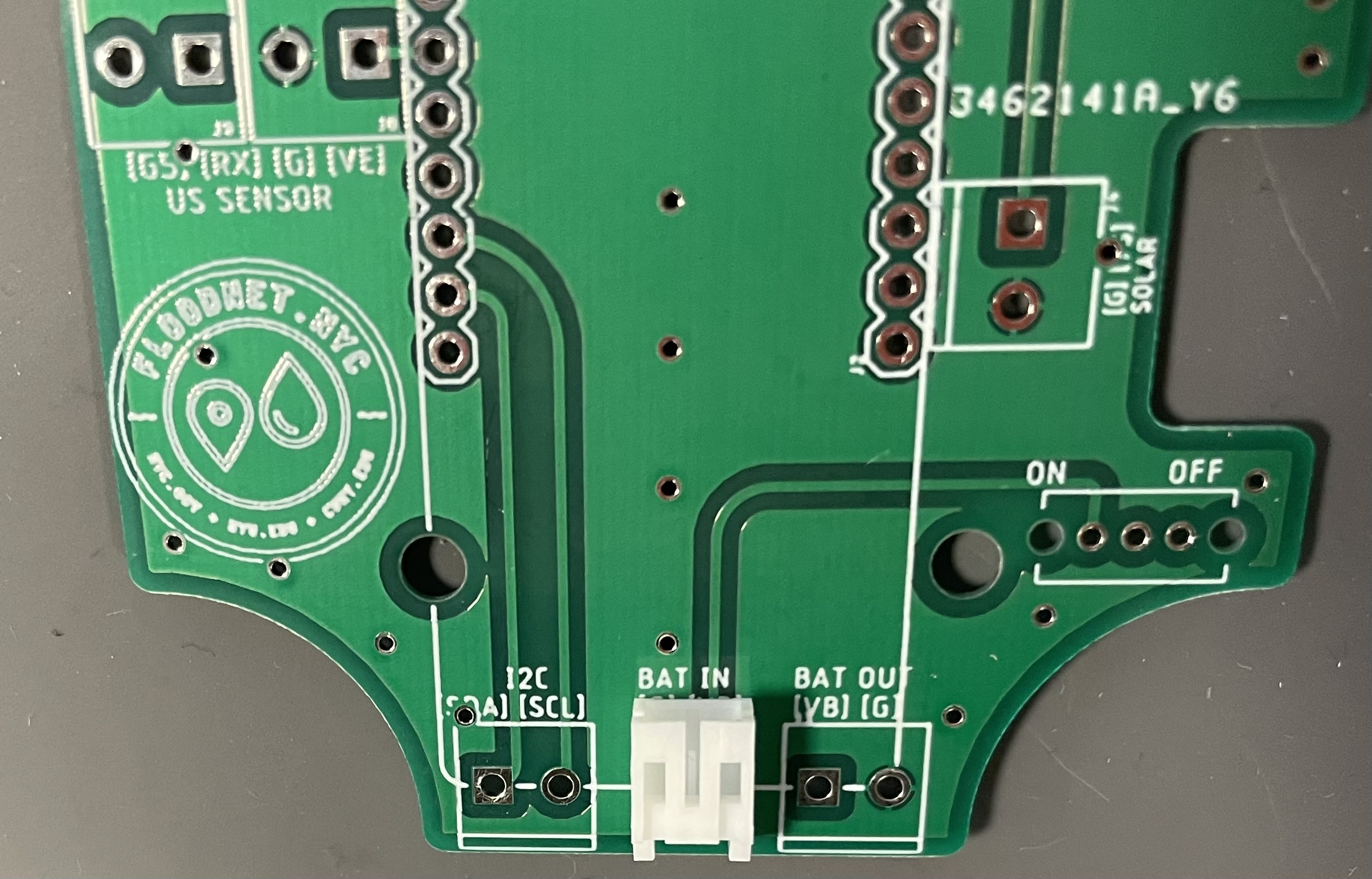
Now with the PCB placed upside down, solder screw terminals for Ultrasonic Sensor and Solar input like shown below.
Note: All the holes of the screw terminal shall be facing the text on the PCB like shown in above figures.
-
Now Solder battery out screw terminals into BAT OUT like below.
-
Using a multimeter check for shorts and connectivity. Further quality of the soldering shall be checked at this step and identify and resolve any soldering errors.
Stage 3 - MCU Assembly
-
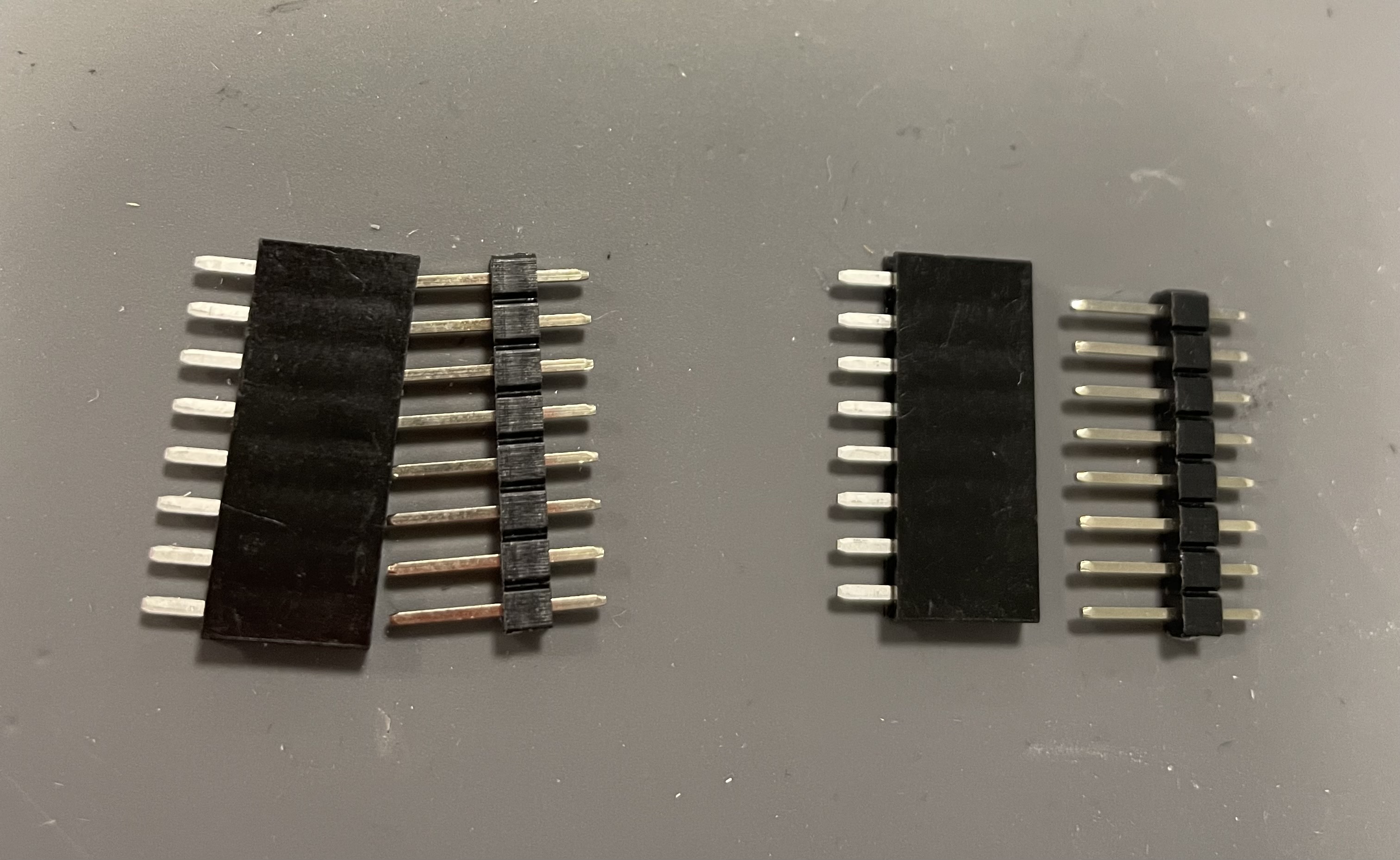
Now cut the MCU male headers to match the 8-pin female headers as shown in the below figure.
-
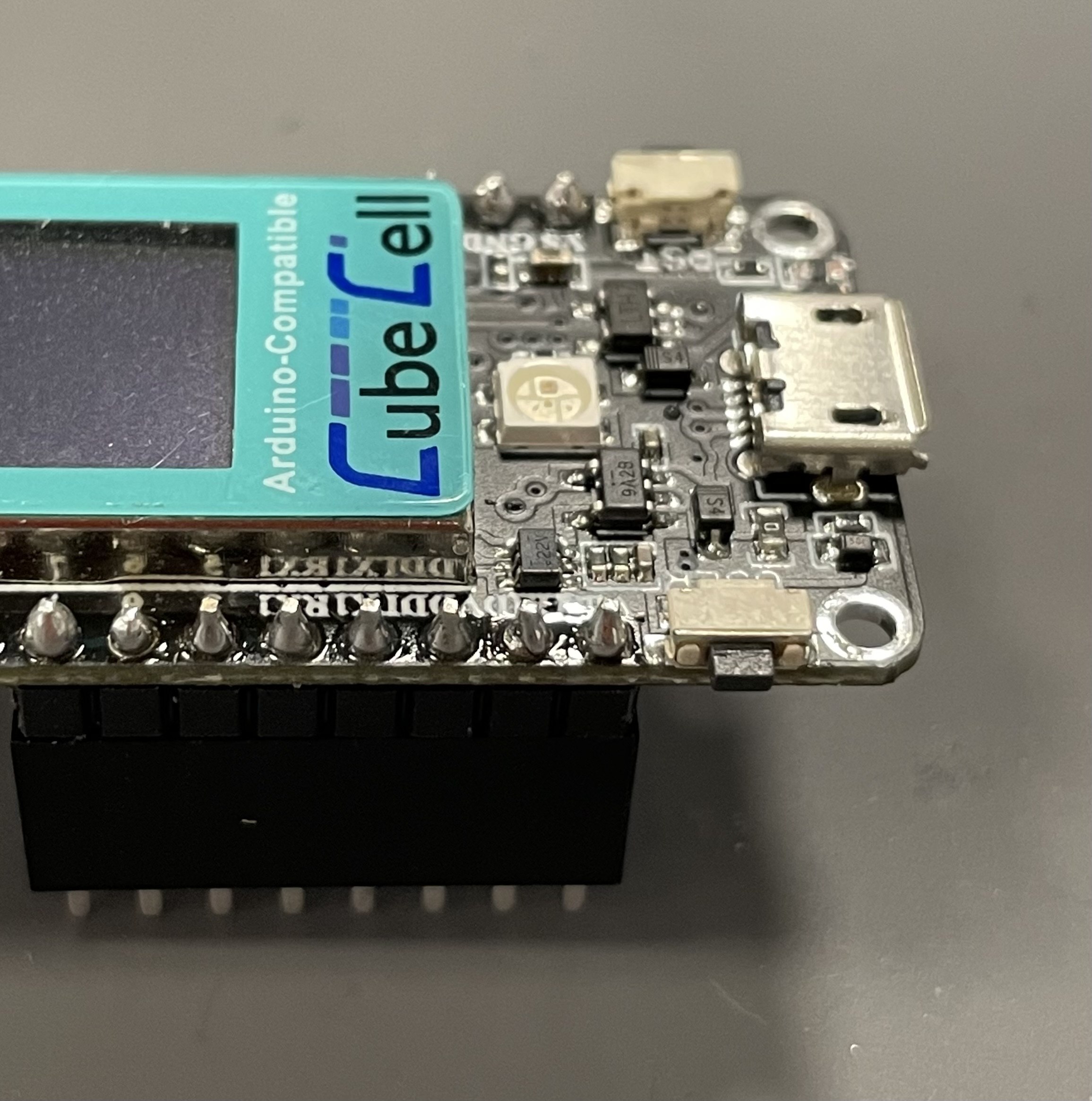
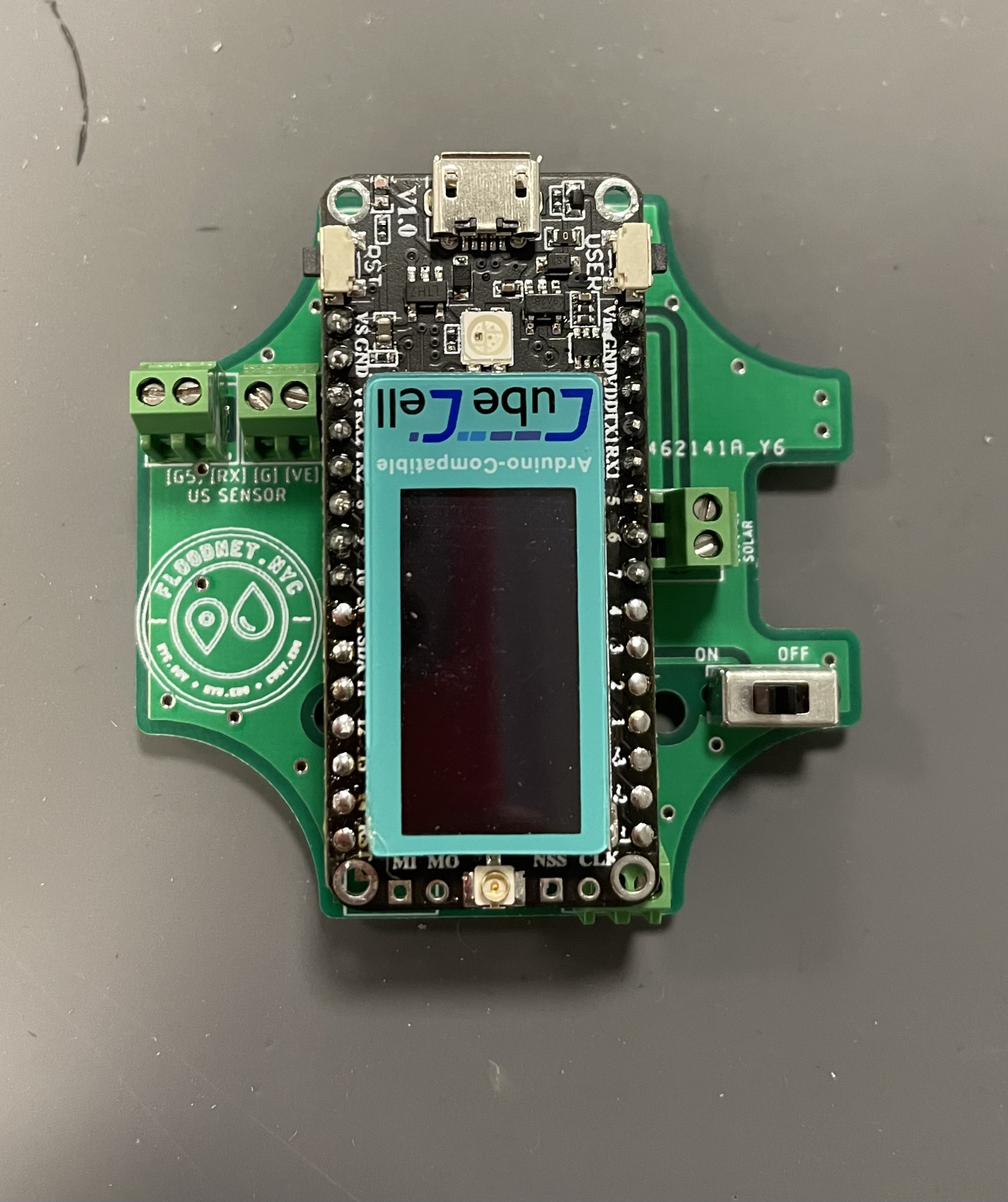
Insert these male headers into female headers and place the MCU’s first eight pins, both sides on top of these male headers. Solder header pins while the MCU is securely held by the female header pins, as shown in the figure below.
-
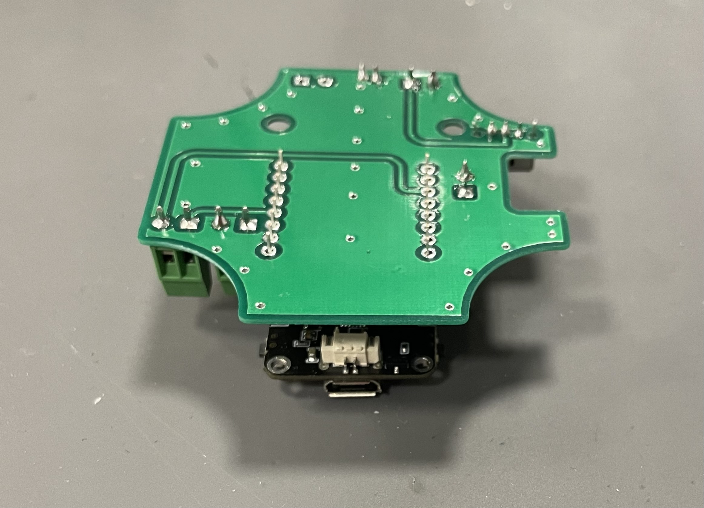
With the PCB upside down solder the female header pins into the PCB like shown below. Make sure PCB is facing the right direction and inserted into the correct pins.
-
Using a multimeter check for the connectivity between the MCU pins and the screw terminals.
Stage 4 - Battery Assembly
-
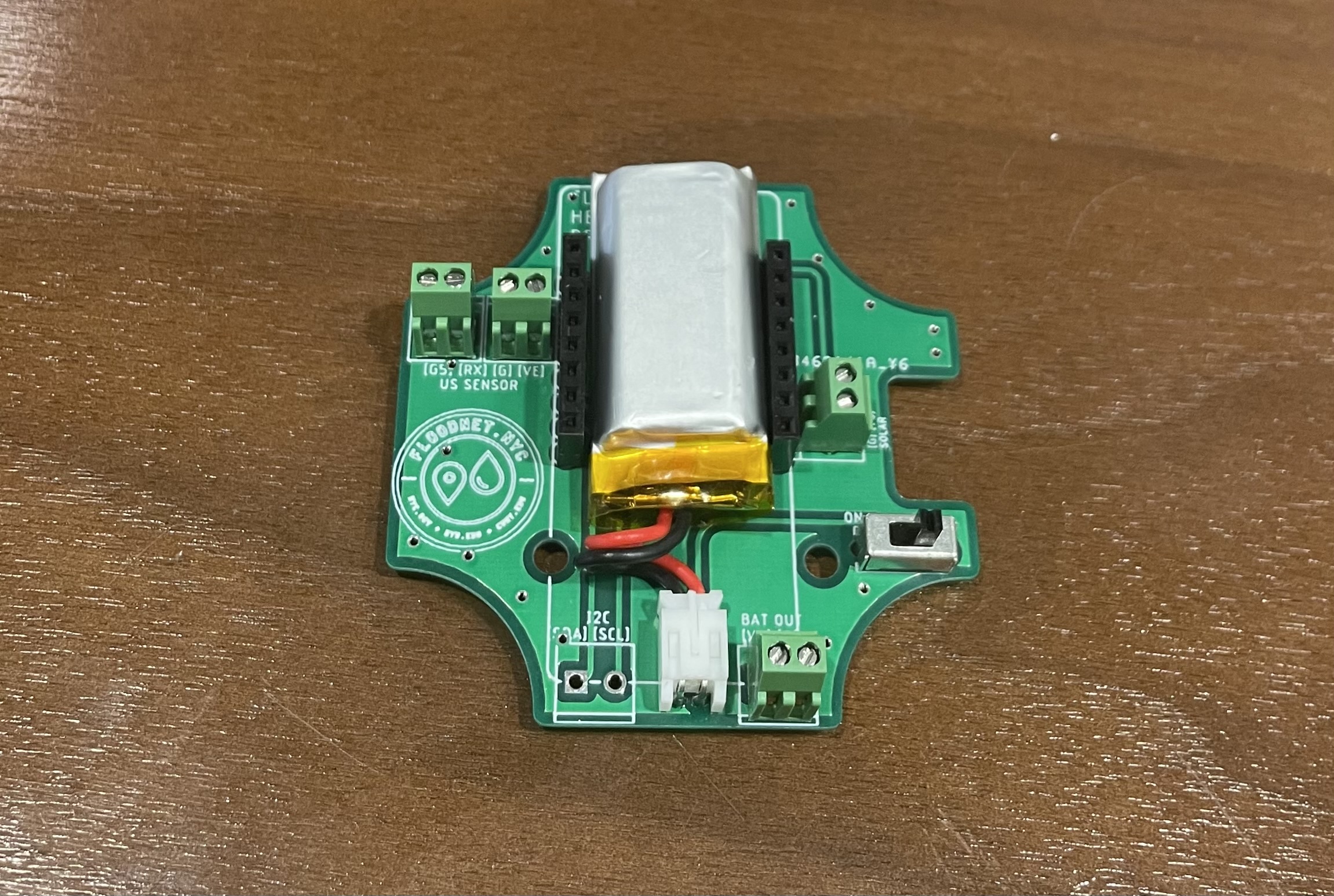
With the switch turned off, remove the MCU from the female header pins and insert a fully charged 400 mAh battery into the BAT IN.
-
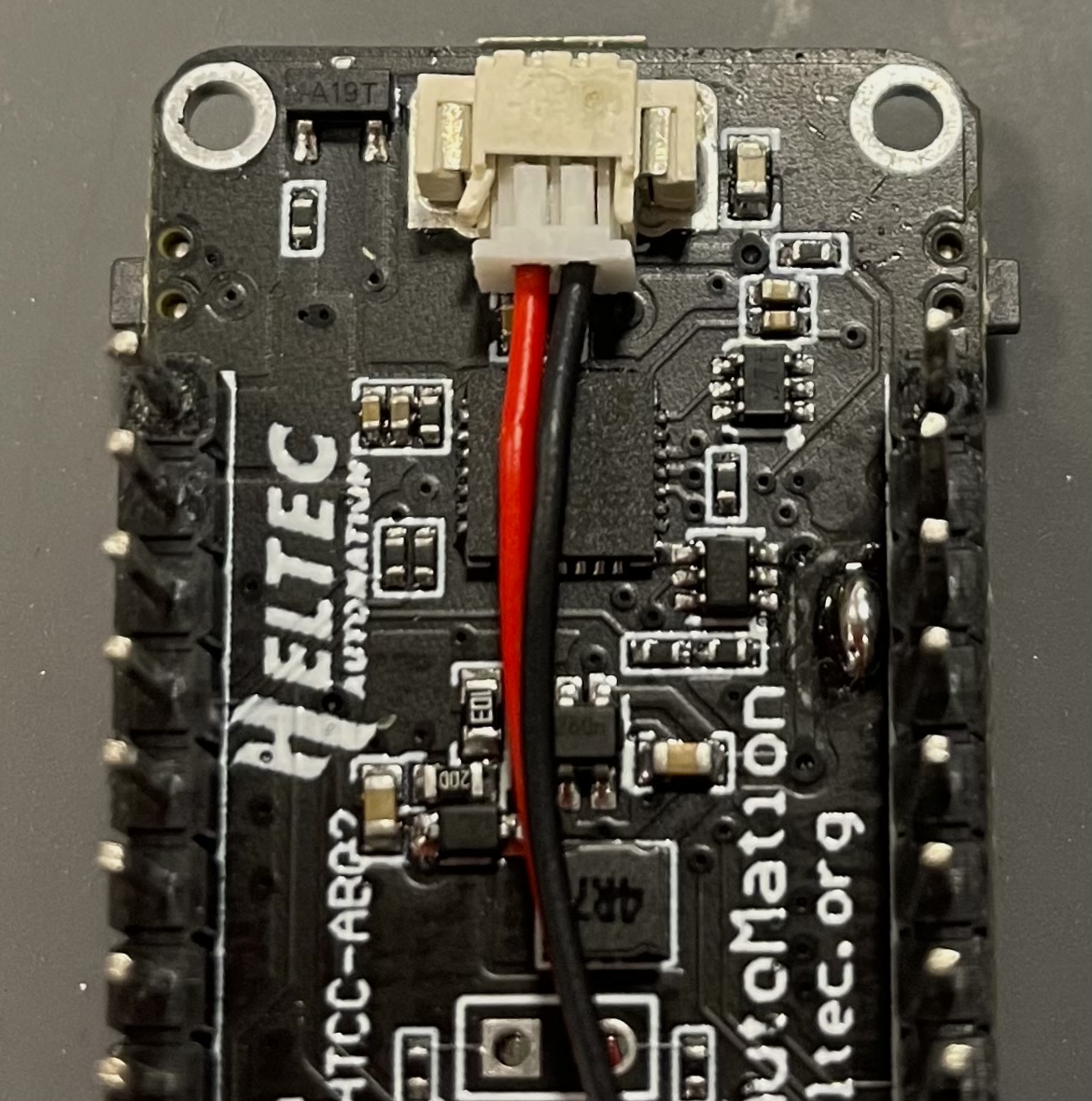
Prepare a 2 Pin JST connector by tanning the other ends. Insert the connecter on the back side of MCU as shown below.
-
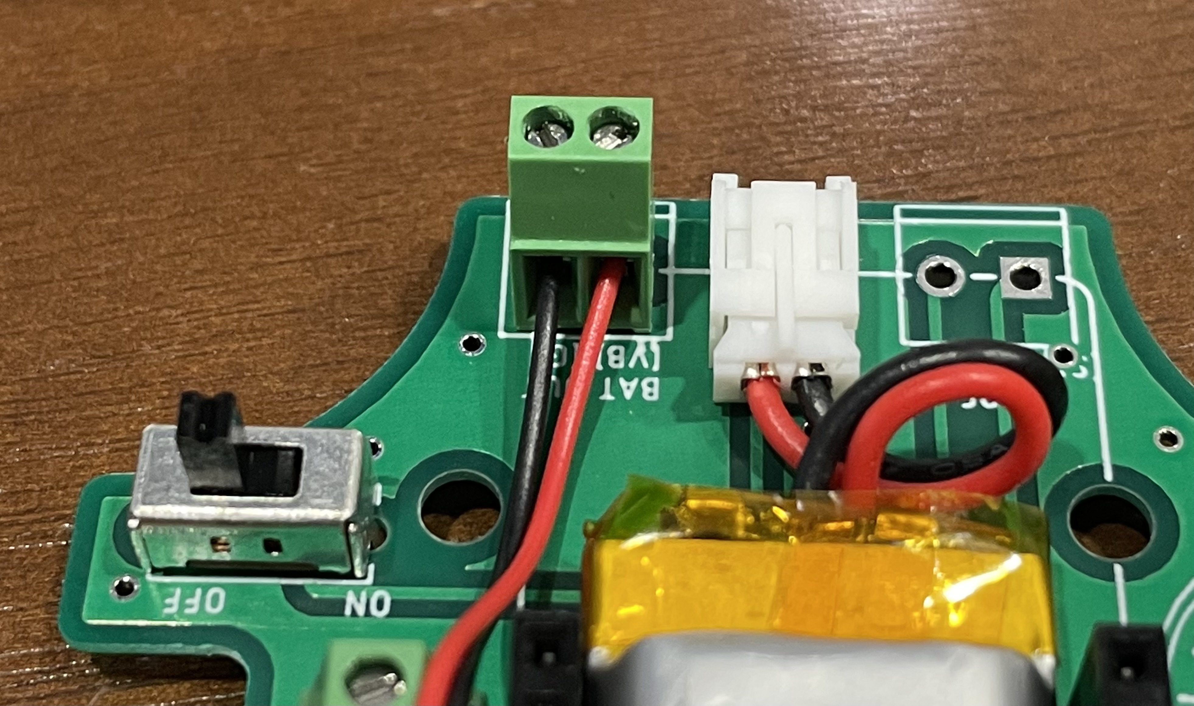
Connect the JST connector with BAT OUT into their corresponding VB and G, respectively, as shown below.
-
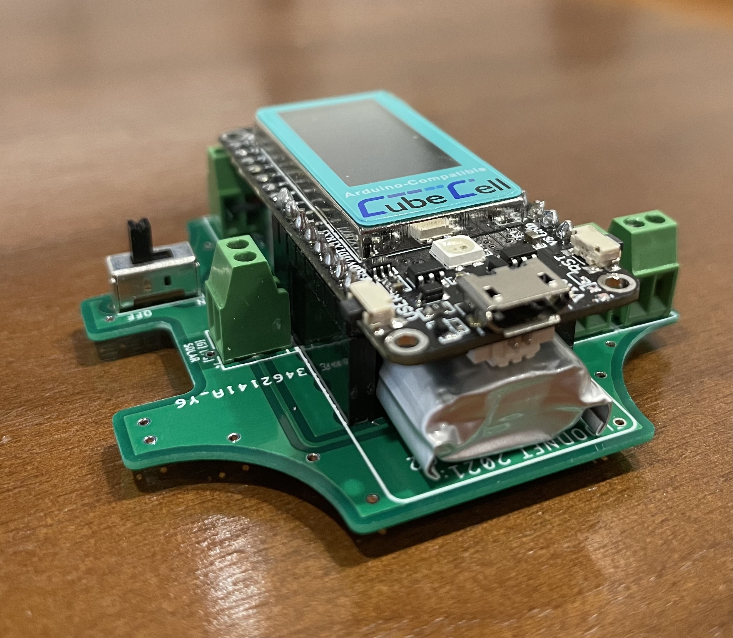
Mount the MCU back onto the headers and make sure the battery is not under any pressure or being crushed by the MCU. When done correctly battery should be only held by the JST connector and sits comfortably under the MCU.
Evaluation 1 - Main voltage check
- Turn on the switch and check the voltage at BAT OUT. The multimeter reading should be VBat - the battery’s voltage level, across VB and GND when the s/w is on.
- Turn off the switch before proceeding to next steps when the evaluation has been successfully completed.
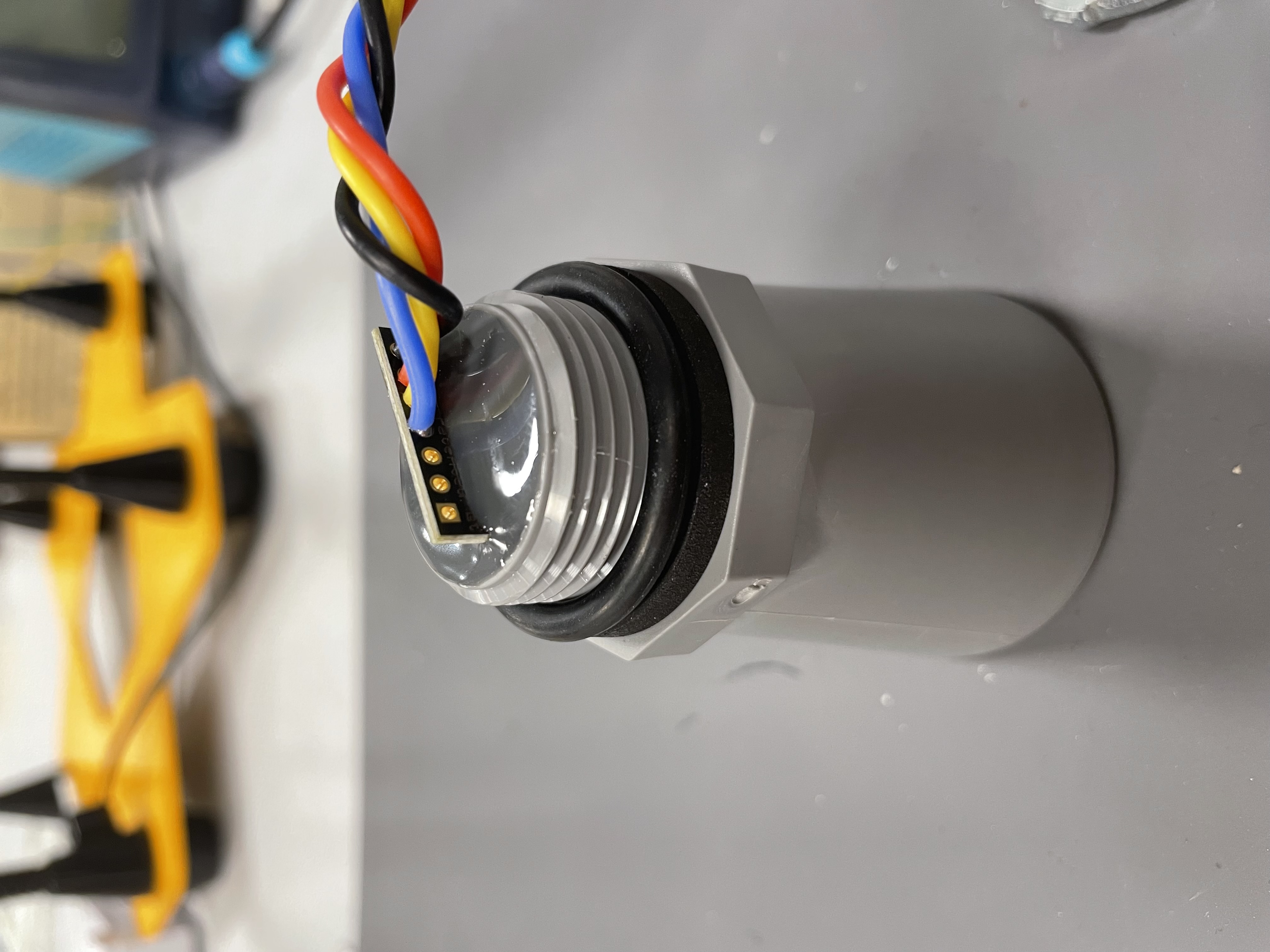
Stage 5 - Ultrasonic Sensor Assembly
-
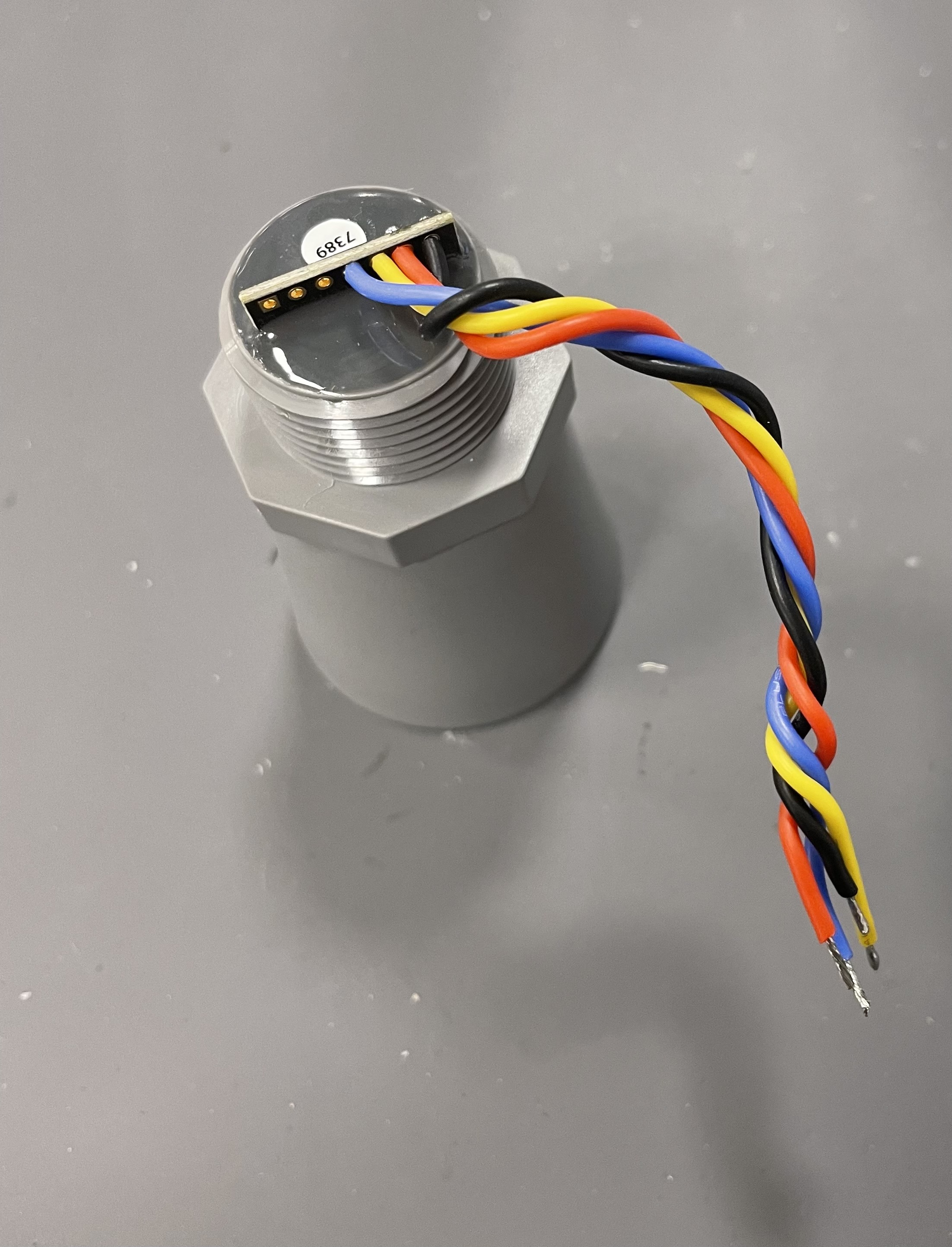
Tan both ends of 4 different colored wires and solder one end of the wires onto the Ultrasonic sensor’s pins - GND, V+, 5 and 4.
-
Carefully, without applying too much pressure on the solder joints, twist them like shown.
-
Check for connectivity and any common soldering errors.
-
Stack 2 washers that come with the lock nut like shown below.
-
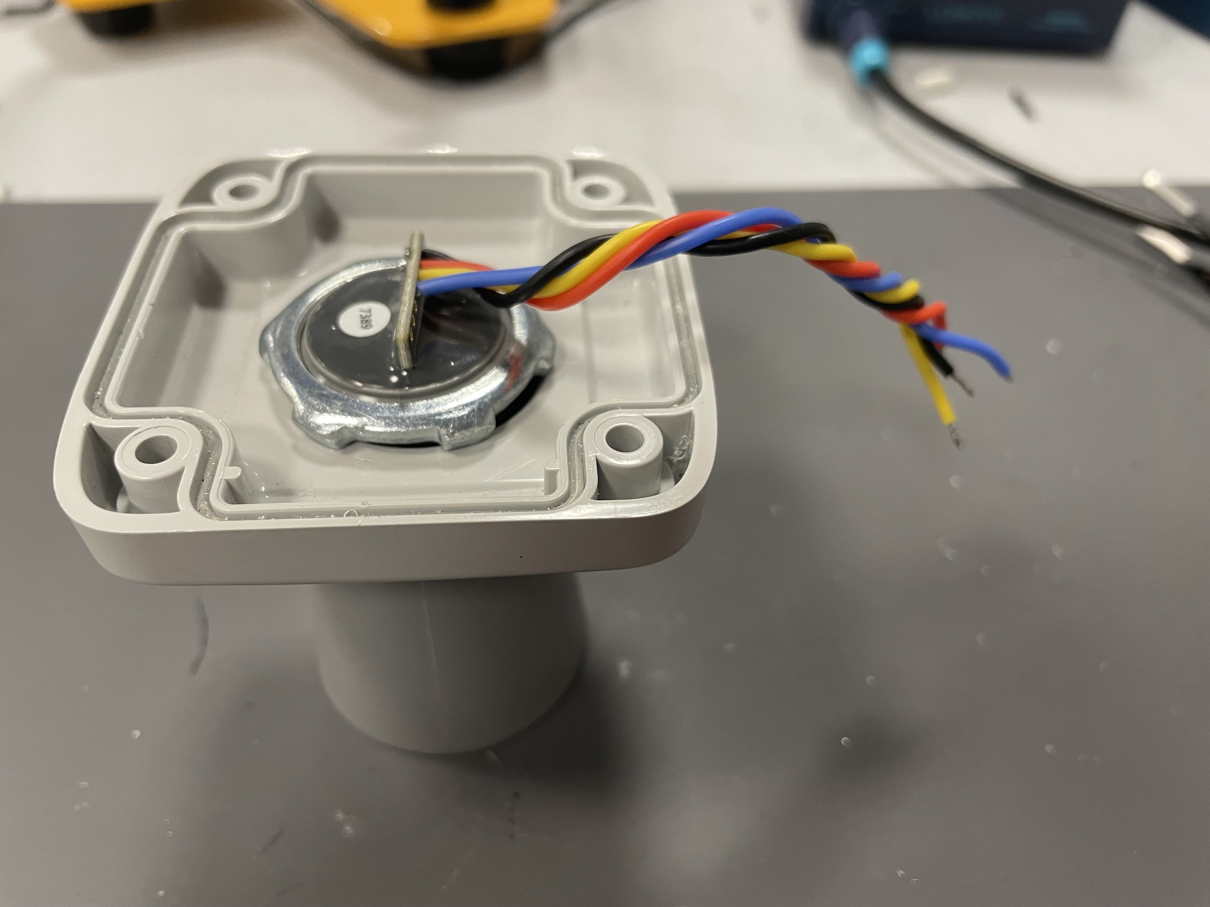
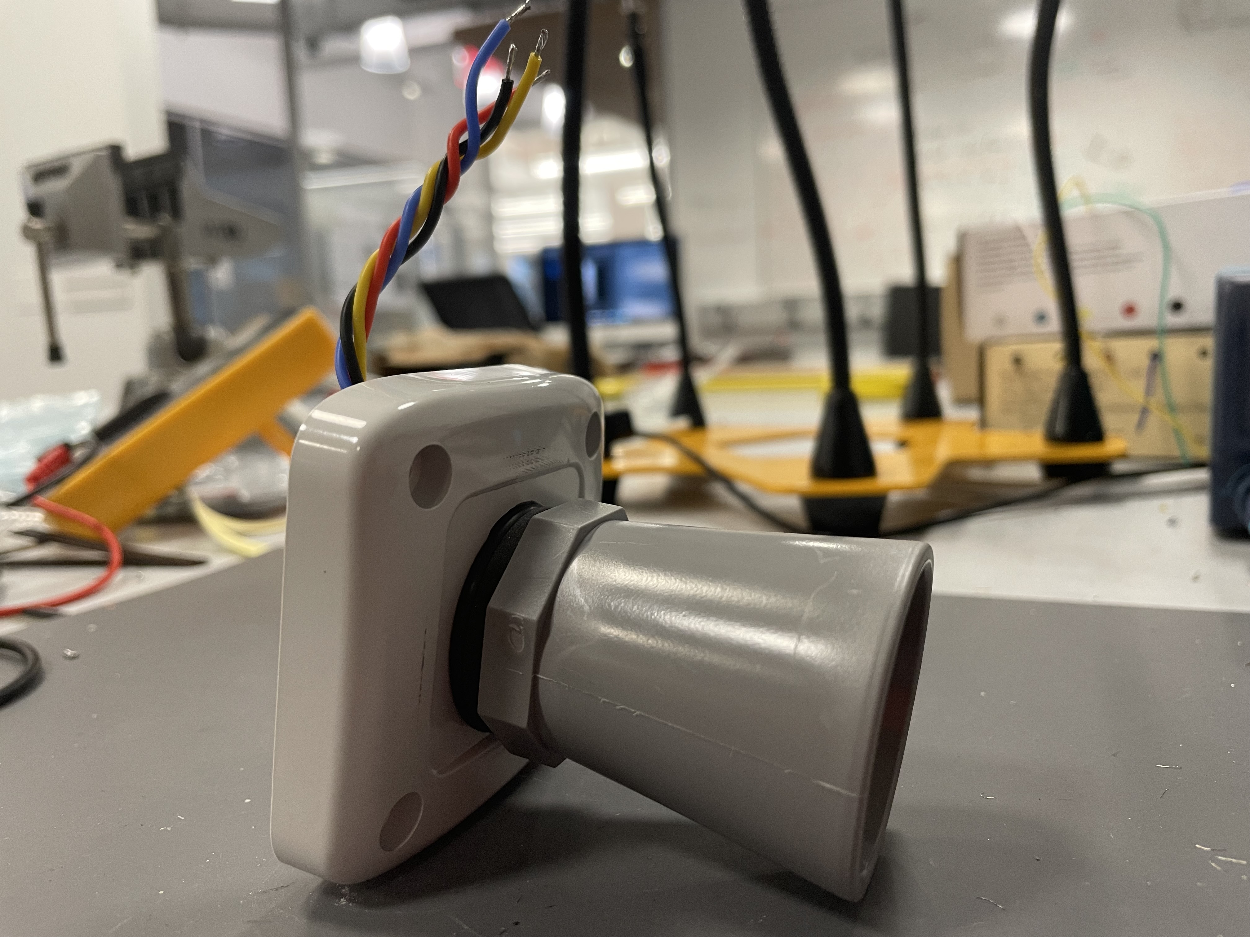
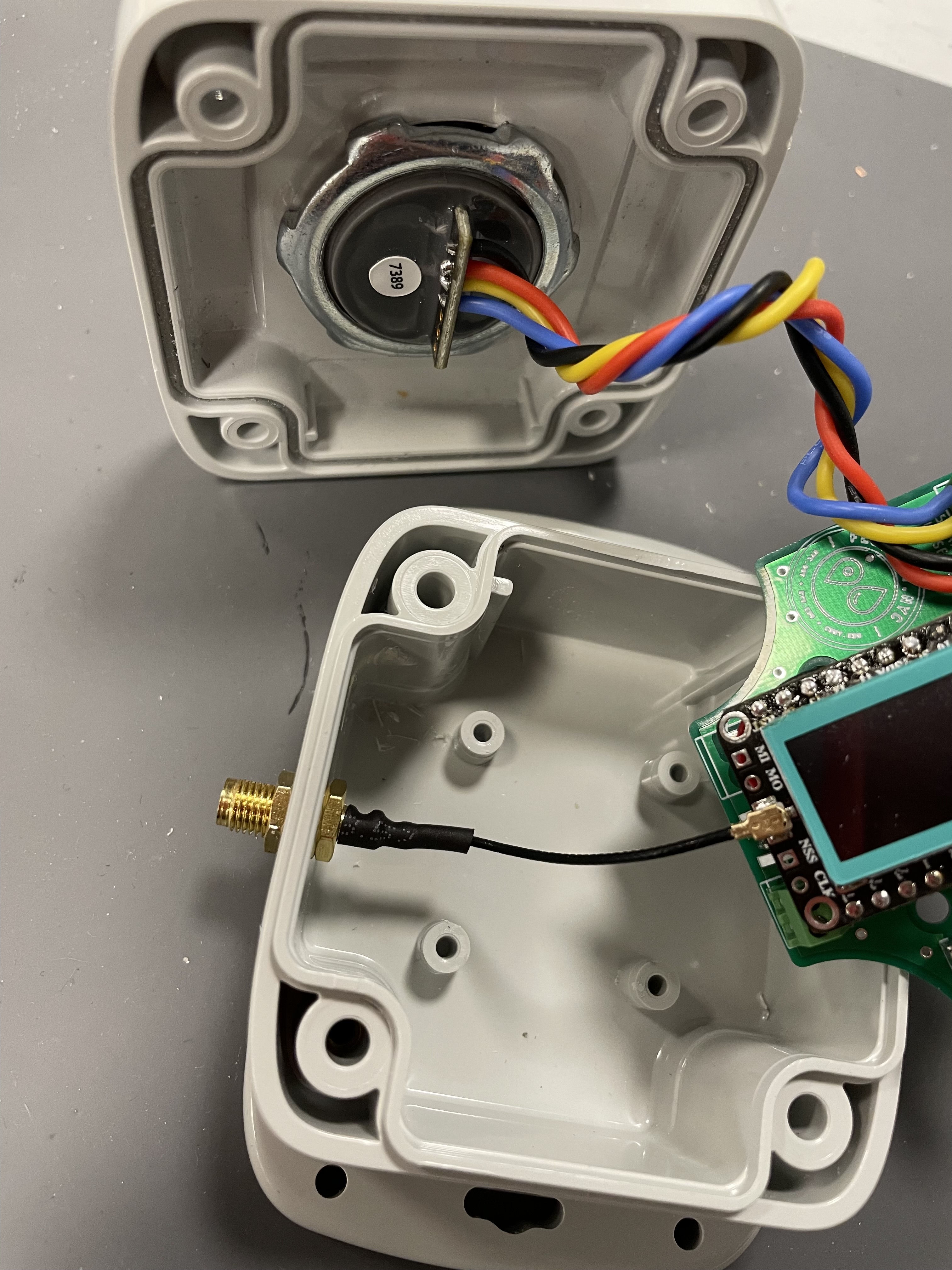
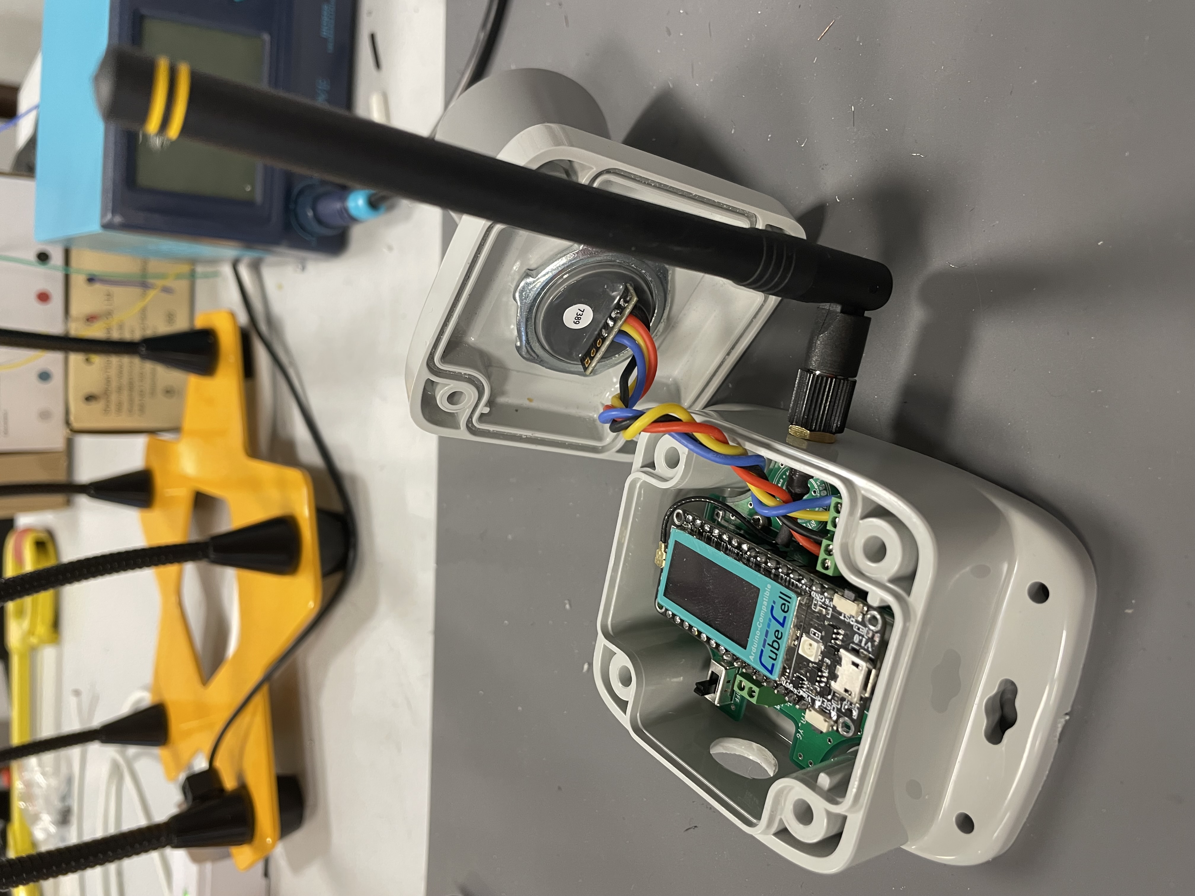
Insert US into the housing lid secure it using a lock nut on the inside of the housing lid.
-
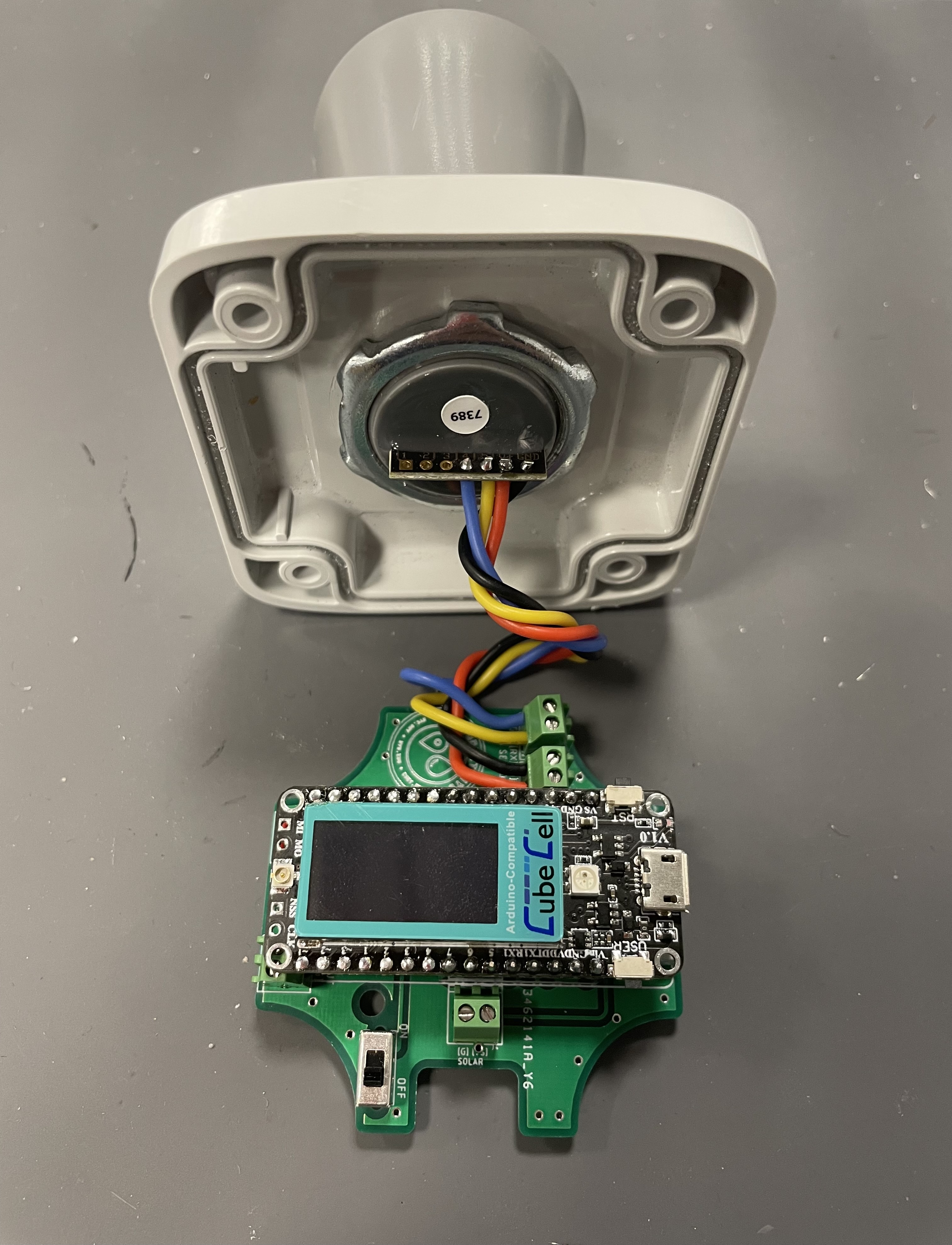
Connect V+ of ultrasonic sensor to the VE of PCB.
Connect GND of ultrasonic sensor to the G of PCB.
Connect pin 4 of ultrasonic sensor to the G5 of PCB.
Connect pin 5 of ultrasonic sensor to the RX of PCB.
Stage 6 - PCB Mounting and Antenna Assembly
-
Using a plier, cut the legs on the bottom of the soldered PCB to save some room.
-
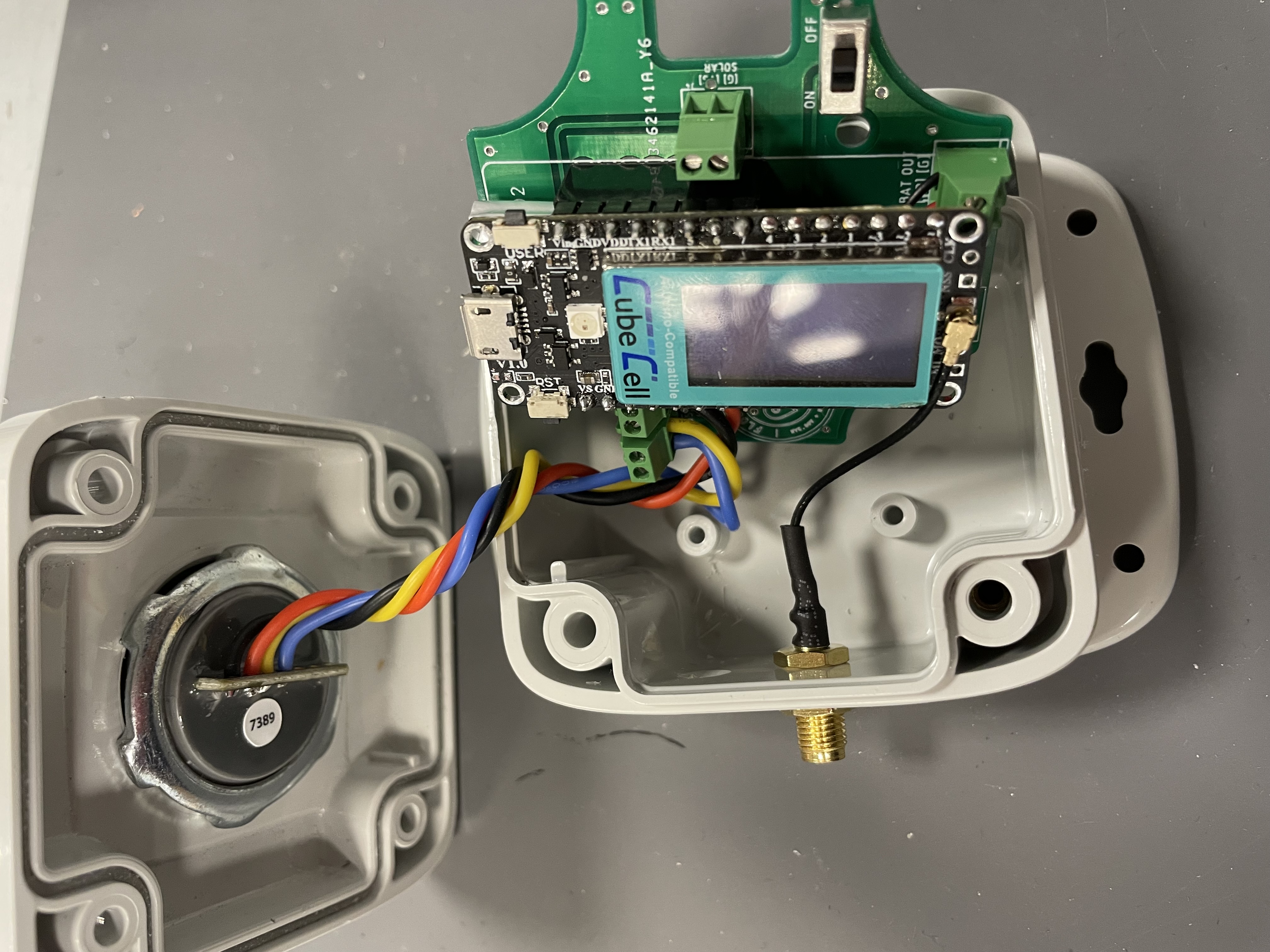
Connect the MHF4 female to the MCU and secure SMA female end into the housing using a nut.
-
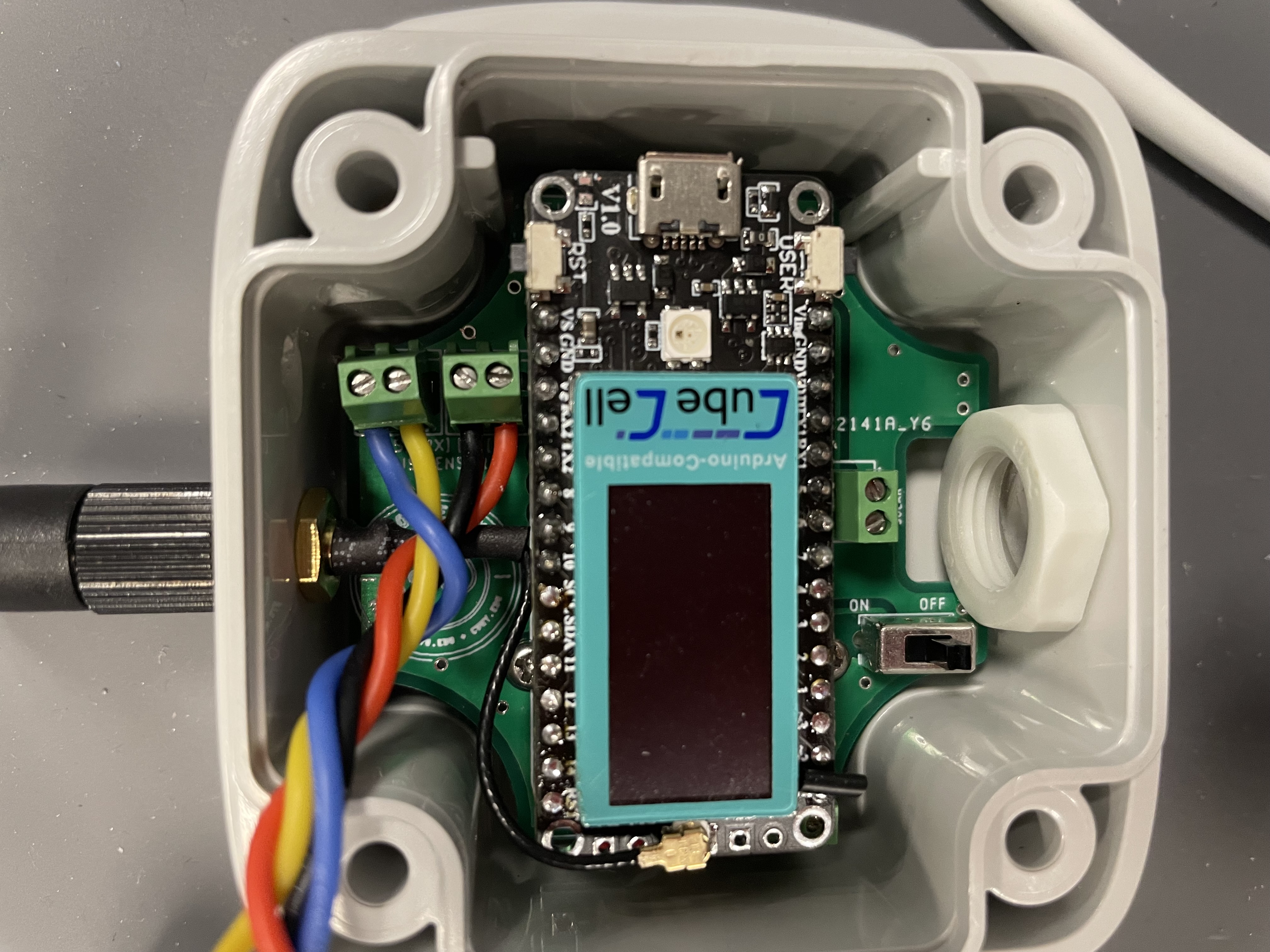
Insert the PCB into the housing by sliding it under the antenna like shown.
-
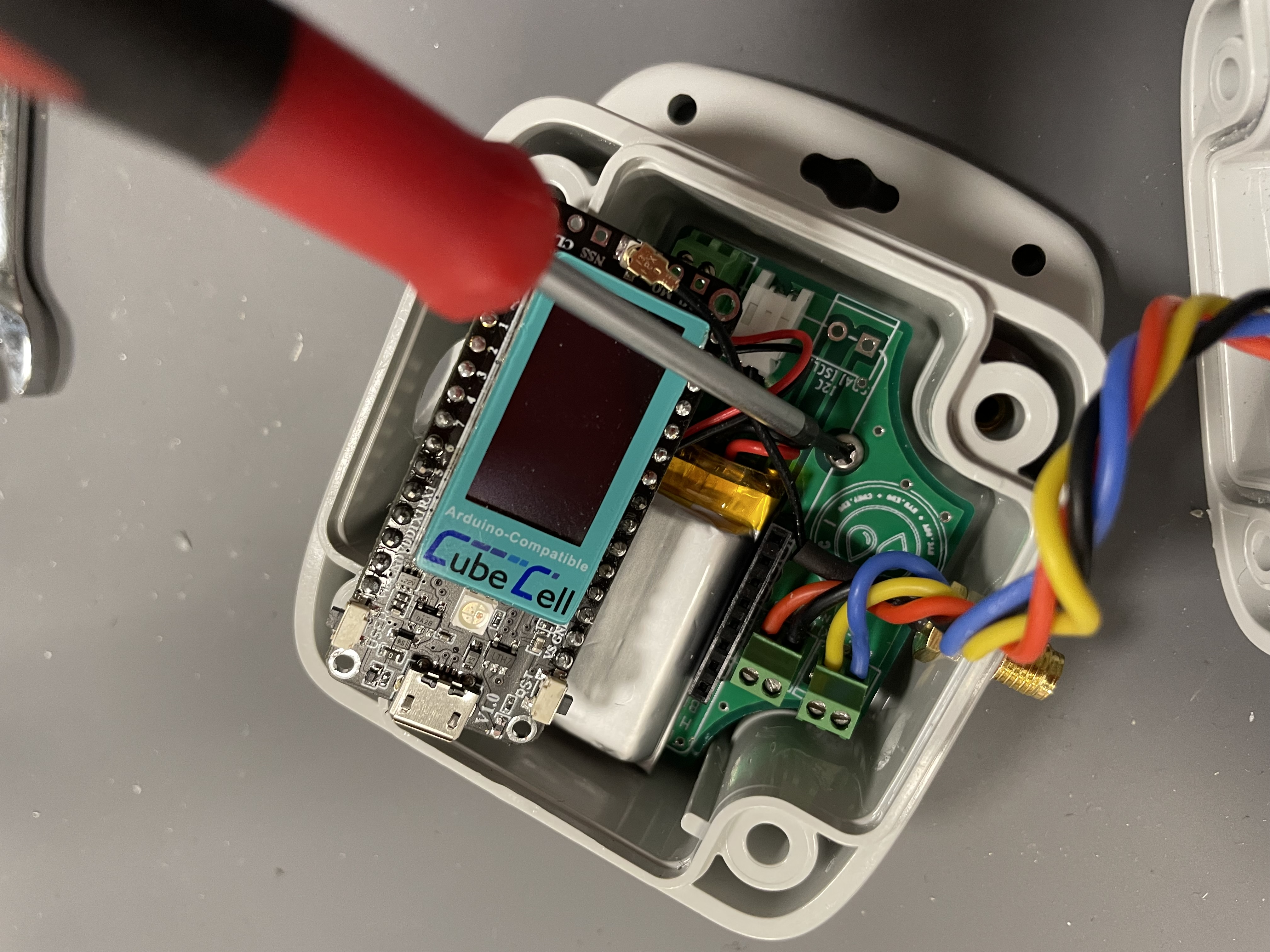
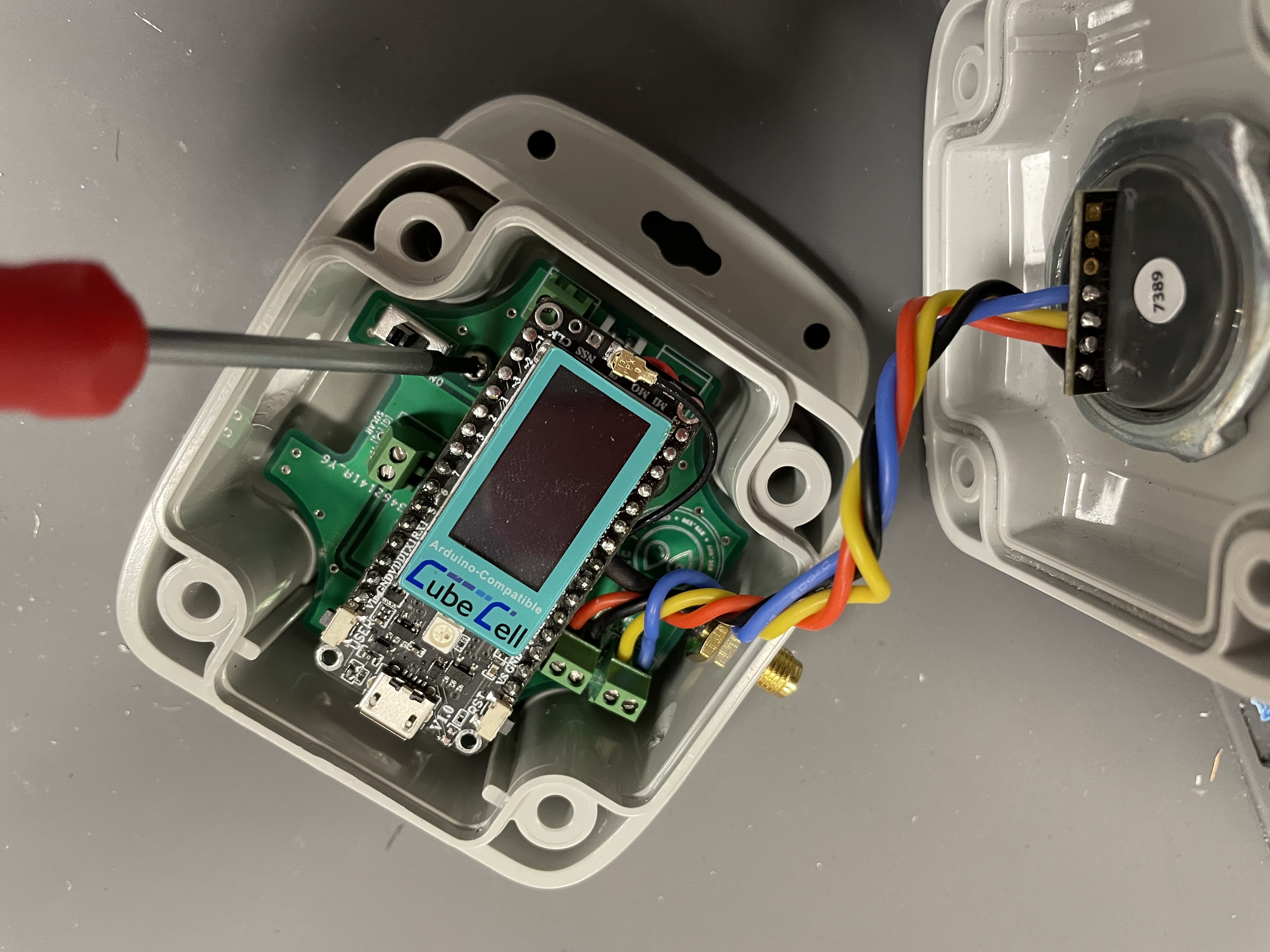
Lift the MCU and screw the PCB onto the mounting headers on the base of the housing. The orientation shall match the housing holes: 1/2” hole shall be facing the solar input.
-
Insert the MCU back into the header pins and screw the other end of the PCB into the housing.
-
Screw in a male LoRa antenna (should support 915 MHz) onto the SMA female connector.
Stage 7 - Solar Panel Assembly
-
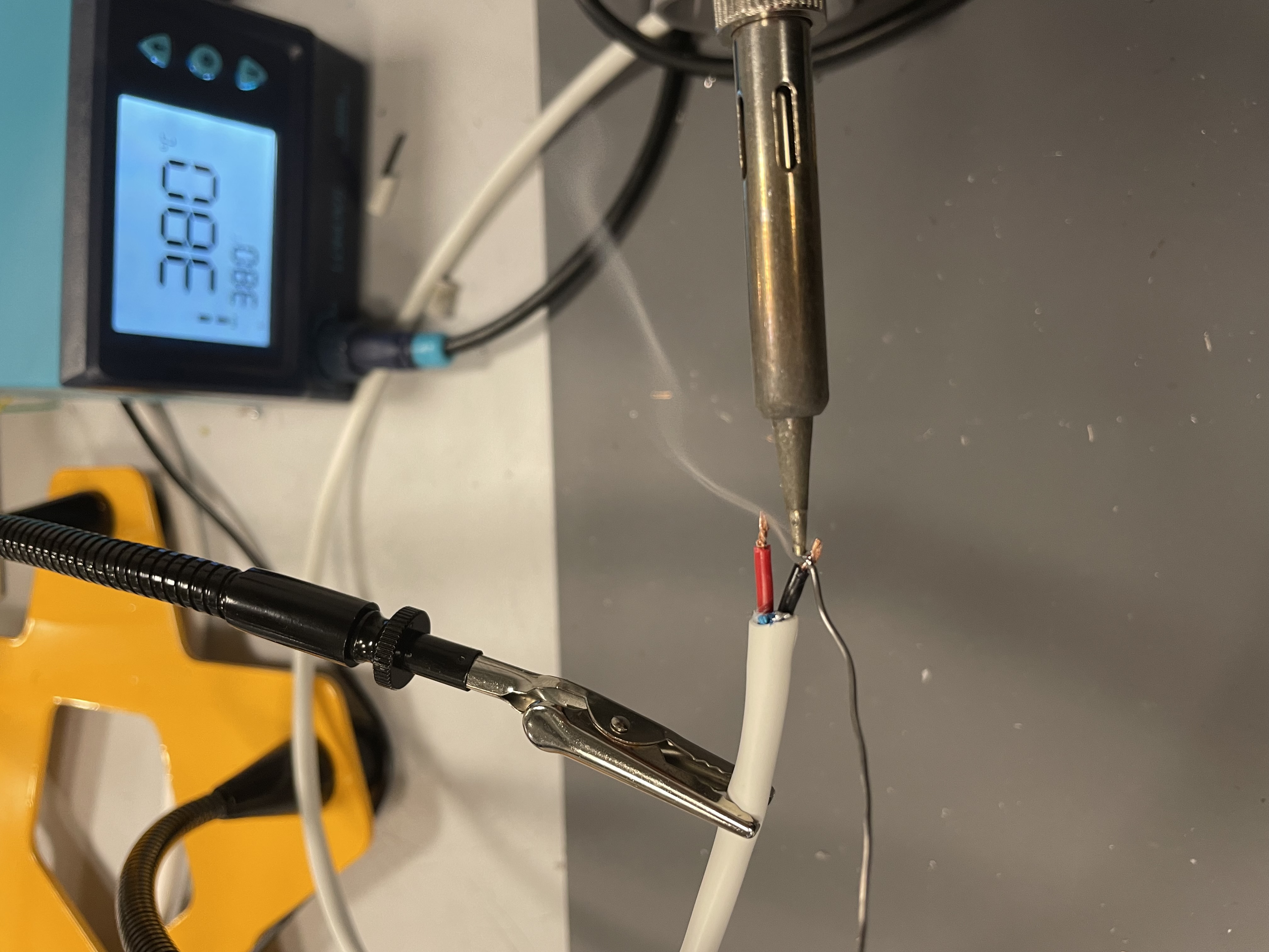
Cut an alarm cable or 2 conductor wire to a length of 30cm or 12 inches. Prepare the ends by tinning them.
Note: Adjust the length so that cable can reach from the sensor to the panel based on the chosen mount.
-
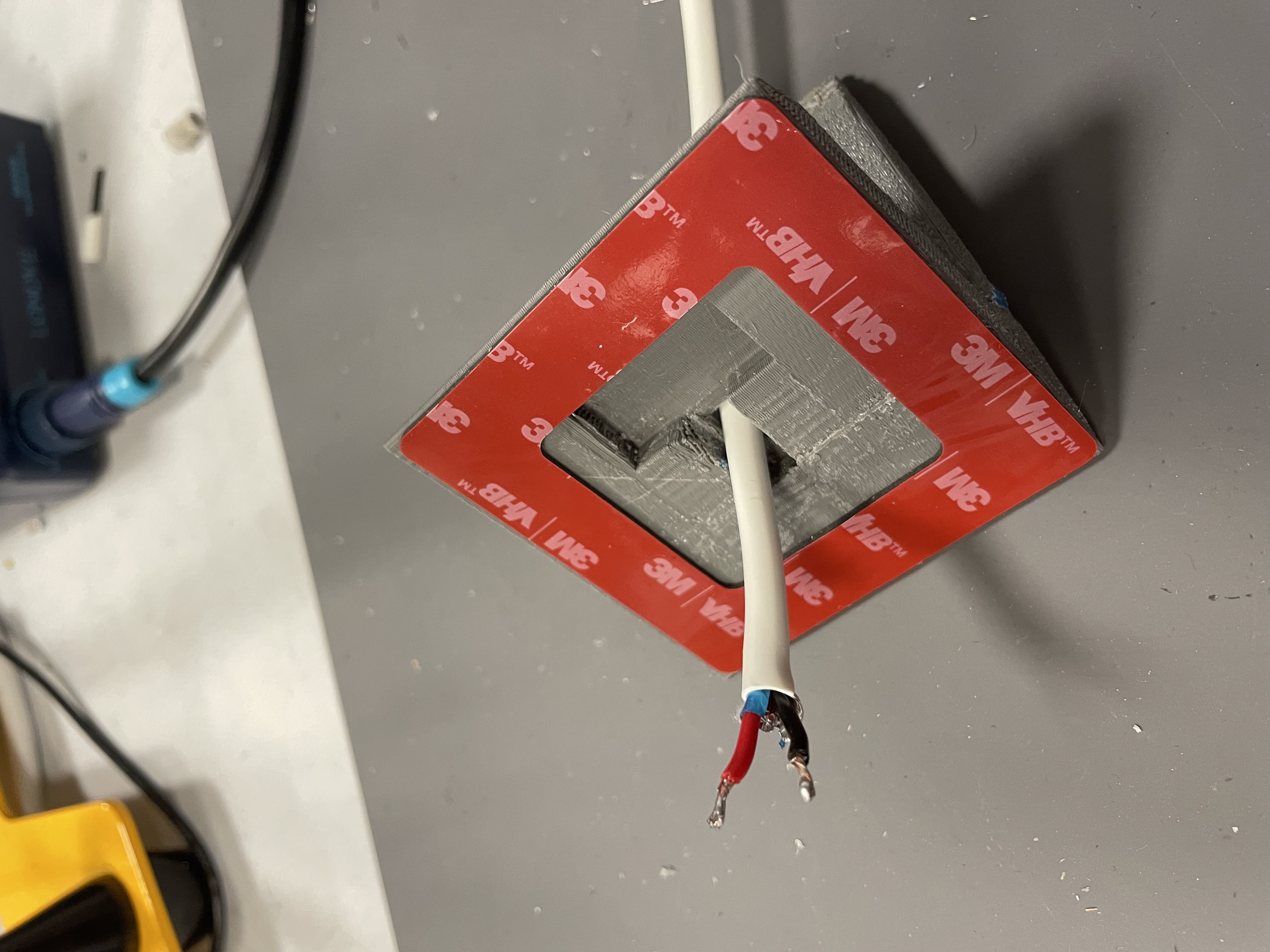
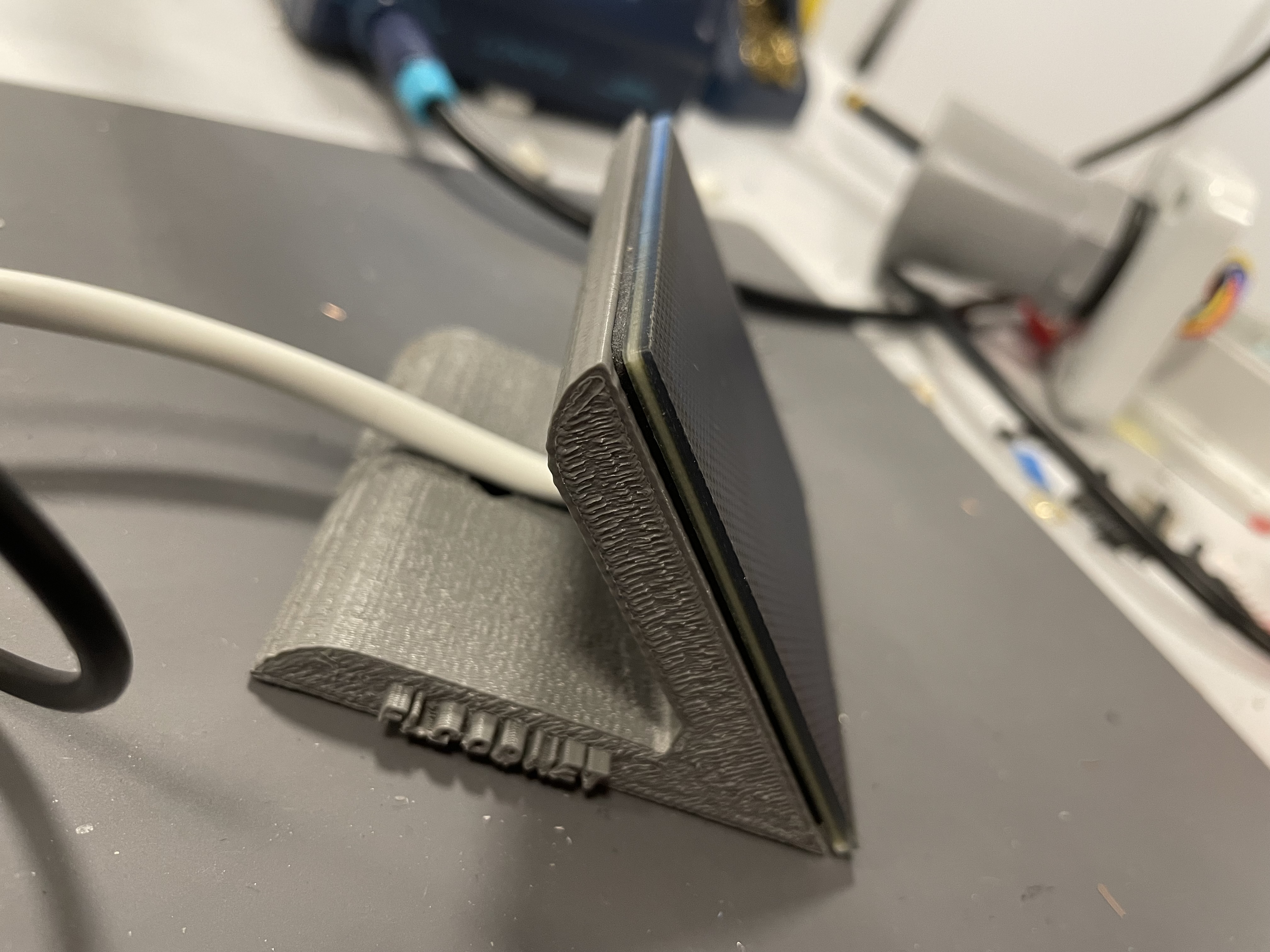
Stick one side of the gasket onto the 3D-mount and run one end of the solar cable through the 3D-mount like shown.
-
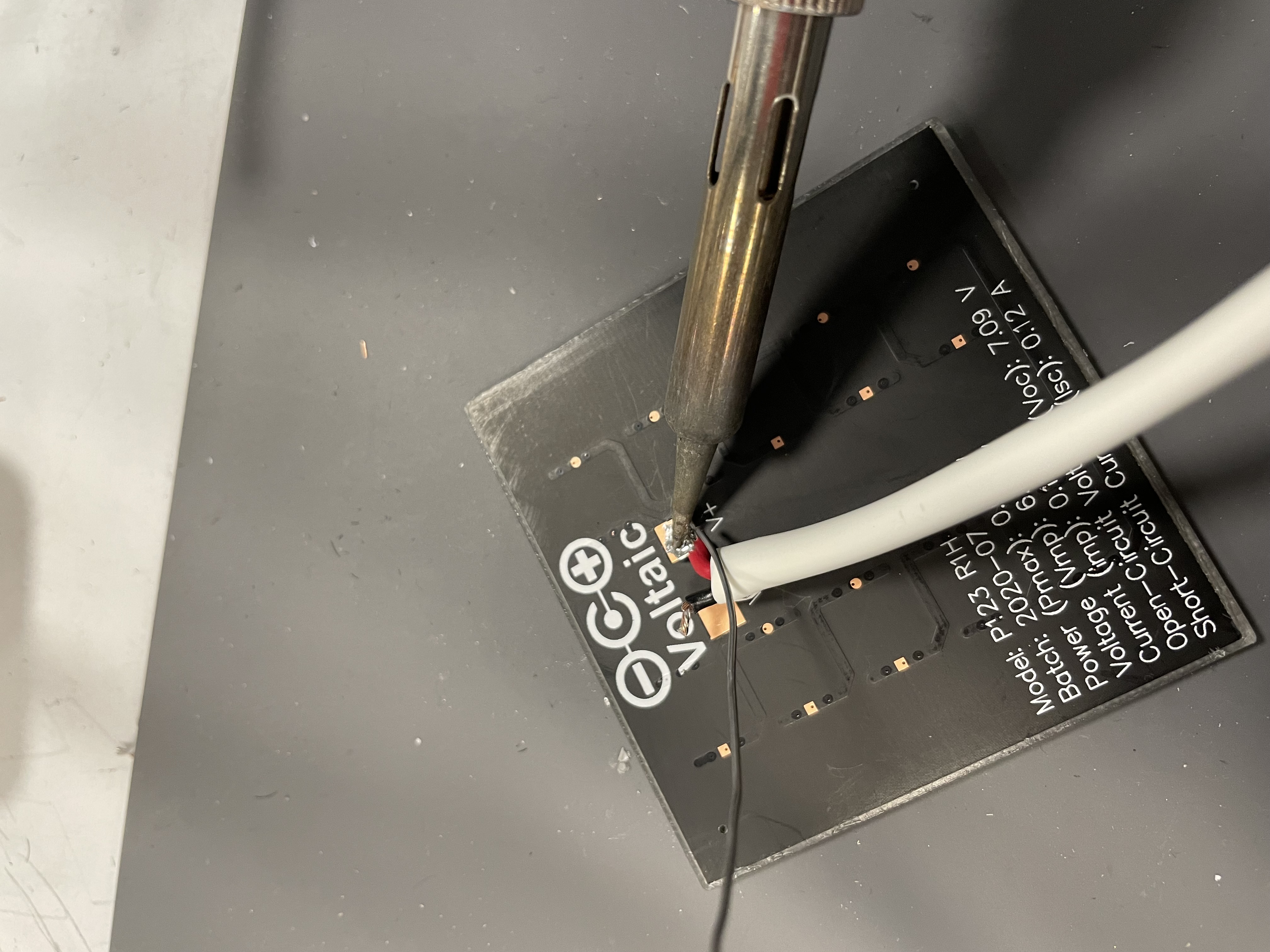
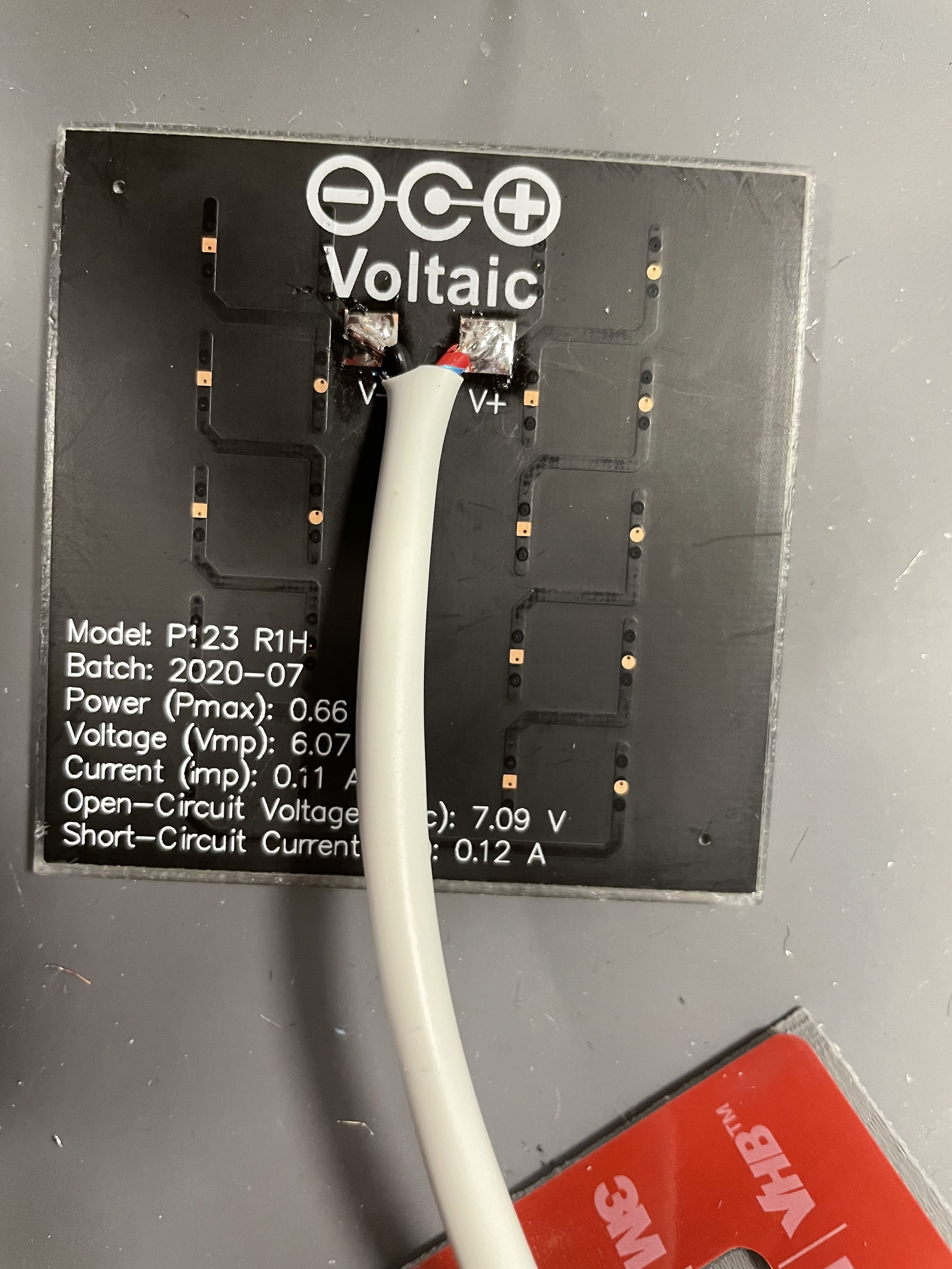
Solder the panel to this end that runs through the 3D-mount and gasket.
-
Seal the panel using the gasket.
-
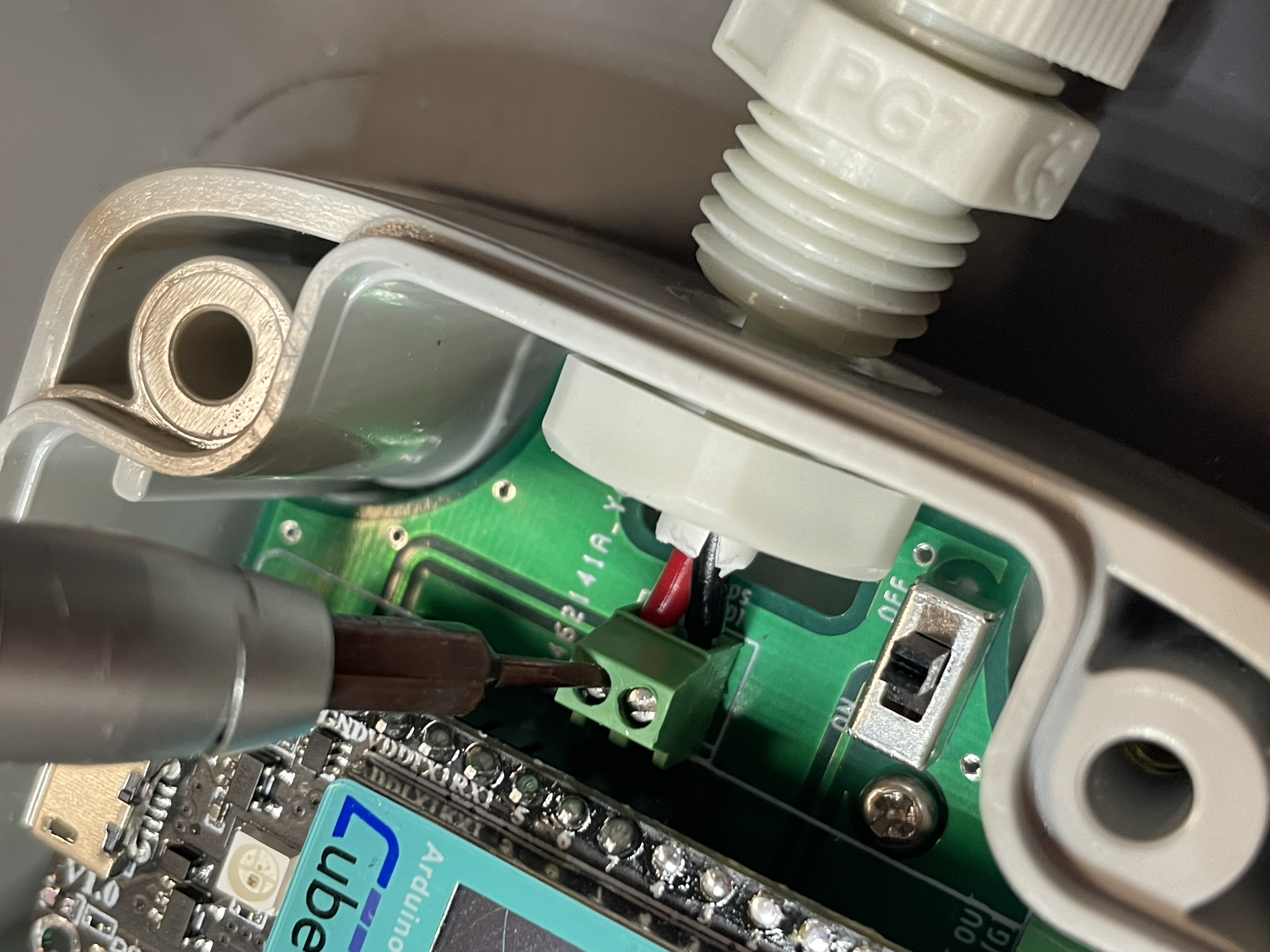
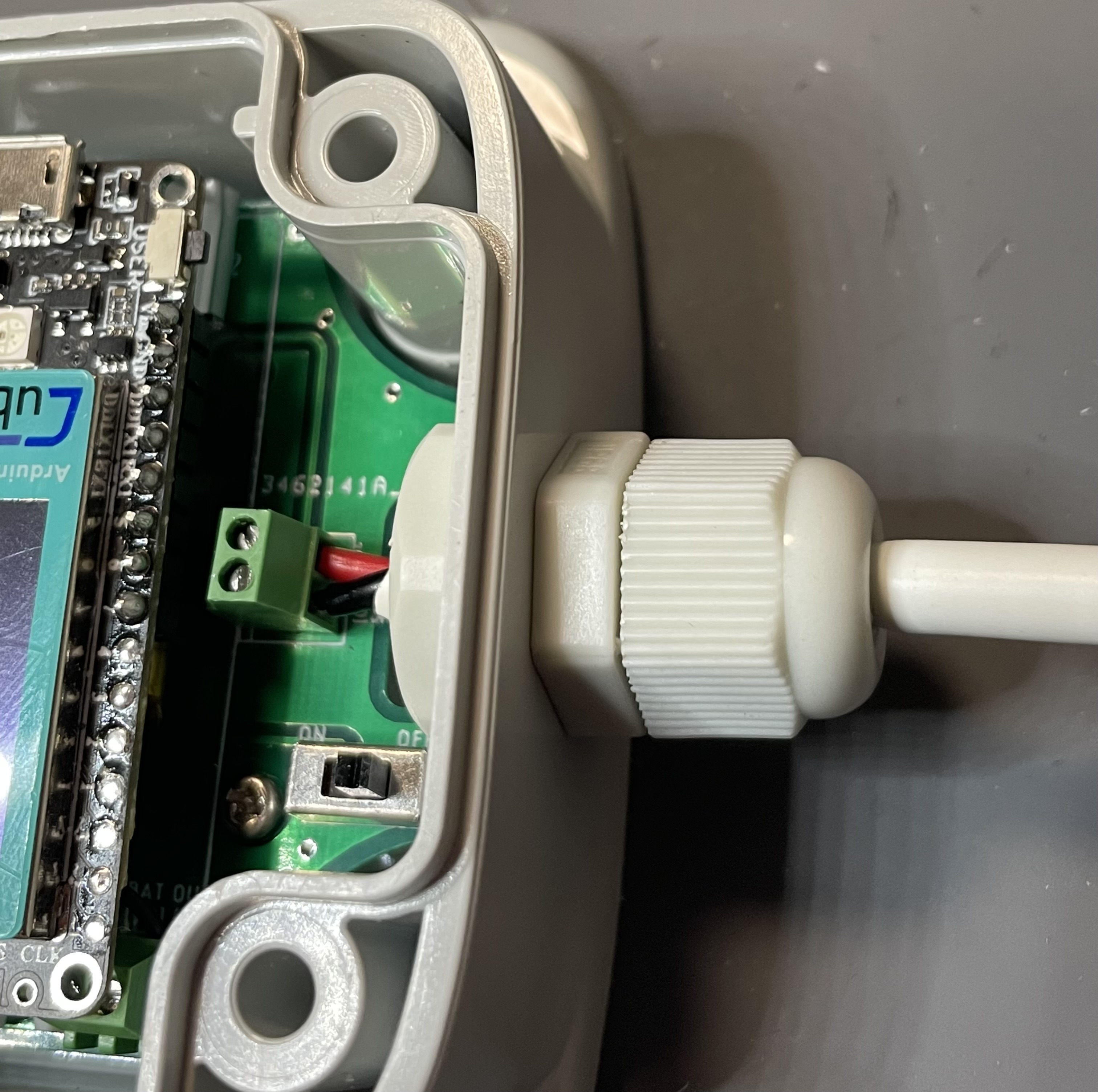
Place the nut of the PG-7 cable gland inside the housing and insert the other prepared end of the solar cable into the housing through a PG-7 cable gland.
-
Screw the open ends of the solar cable into the screw terminal SOLAR. Secure the cable gland.
Evaluation 2 - Solar Panel Operation
- Check for connectivity between both the ends of the solar cable. Also check for shorts between the VS and GND.
-
Flash light onto the solar panel and check voltages on the screw terminals using a multimeter. When a phone falshlight is flashed upon the panel, it should read atleast 3 Volts.
- Now with the light is being flashed onto the panel, verify the VS is the positive terminal. If not, the solar panel has been soldered in reverse and shall be re-soldered so that a positive voltage is seen across VS and GND.
Evaluation 3 - Sensor Operation
- Flash the test firmware and check the battery voltage and ultrasonic measurements on TTN console. The battery voltage shall be between 3.7 Volts and 4.2 Volts. Since we would be using a fully charged battery, it should read voltage greater than 4 Volts. The distance reading on the TTN console shall be greater than or equal to 300 and less than or equal to the maximum range of the sensor model. The 5-meter model range is 300mm to 5000mm and the 10-meter model range is 300mm to 10000mm.
Final steps
- Close the lid and make sure the ultrasonic sensor wires goes into the space safely to avoid them being in the way.
- Now secure the lid with screws
- The sensor shall feel robust and when invereted there shall be no moving parts.
- Inspect the sensor mechanical quality of the following: holes, mounts, securing enclosure, waterproofing.
